
Page 81 - Analog and Digital Filter Design
P. 81
78 Analog and Digital Filter Design
Cauer Response
The Cauer response has ripple in the passband and in the stopband. Cauer filters
are used where it is necessary to have a sharp transition between the passband
and stopband, that is, a very steep skirt response. The drawback is that the filter
circuit is more complex: passive filters require series or parallel tuned sections;
active filters require three or four operational amplifiers per section. A further
drawback is that, because of the sharp transition between the passband and
stopband, the phase of the output signal changes rapidly close to the cutoff fre-
quency, which results in a large group delay variation. This type of filter will not
be suitable for handling pulsed signals if one of the harmonics frequencies coin-
cides with a peak in the group delay.
Cauer filters are named after a German scientist, W. Cauer, but are commonly
called elliptic filters because elliptic integrals are used in the calculation of their
transfer function. Tables of normalized component values and pole-zero posi-
tions have been published by Zverey3 and their use is reasonably simple. His
tables show the attenuation that can be expected for a given set of values. For
the average user these tables are entirely adequate for the design of both active
and passive filters.
Amstutz4 has published computer programs that calculate pole, zero, and com-
ponent values for both symmetrical (odd-order) and nonsymmetrical (even-
order) filters. These programs will not be described here; readers interested in
pursuing this subject further are recommended to read Amstutz’s article and
an explanation given by Cuthbert’ (who has published a BASIC version of
Amstutz’s FORTRAN program).
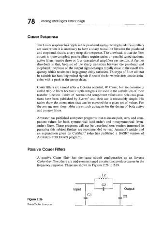
Passive Cauer Filters
A passive Cauer filter has the same circuit configuration as an Inverse
Chebyshev filter; there are mid-element tuned circuits that produce zeroes in the
frequency response. These are shown in Figures 2.26 to 2.29.
Input ThT
output
Figure 2.26 T T
Third-Order Lowpass