
Page 78 - Analog and Digital Filter Design
P. 78
Time and Frequency Response 75
Input ~I+'C'21l~n,,t,ut
i i
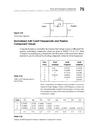
Figure 2.25
Third-Order Highpass L" L'3
Normalized 3 dB Cutoff Frequencies and Passive
Component Values
Using the formula to normalize the lowpass filter design to give a 3 dB cutoff fre-
quency, recalculated component values are given in Tables 2.25 to 2.27. Table
2.24 gives normalizing mlds frequencies that were used in the conversion; denor-
malization can be achieved by dividing component values by these frequencies.
Filter 20 dB 30 dB 40 dB
Order Stopband Stopband Stopband
3 0.65 0.47233 0.33229
4 0.77384 0.63008 0.49672
5 * 0.73314 0.61882
Table 2.24 6 0.88763 0.80 10 1 0.70627
*
8 0.87924 0.81470
3dB Cutoff Frequencies for 10 * * 0.87438
Some Filters
Note: * indicates that Huelsman did not publish component
values for these designs. These cutoff frequency values can
be calculated easily using the formula given, but they were
not required to produce the following tables of normalized
component values.
Order I C1 L2 c2 c3 LA c4 c5 16
3 0.76162 1.52324 0.20803 0.76162
4 0.39649 1.21732 0.40753 1.53955 0.71872
6 0.059471 0.75761 0.48265 1.27903 0.78414 0.93651 0.63648 0.43328
L' 1 C'2 L'2 L'3 C'4 1'4 1'5 C'6
Table 2.25
Passive 20 dB Stopband Inverse Chebyshev Component Values