Page 292 - Analysis and Design of Machine Elements
P. 292

Analysis and Design of Machine Elements
                   270
                         For a stepped shaft with individual cylinder length l and torque T , the unit length
                                                                                 i
                                                                     i
                       angular deflection can be estimated from [4]
                                             z
                                        4 1  ∑ T l
                                                 i i
                                = 5.73 × 10                                              (10.20)
                                         LG     J i
                                             i=1
                                                                                      4
                                                                                             4
                       where J is polar moment of inertia of circular cross section of a shaft, J =   d /32, mm ;
                       L       –shaft length subjected to torsion, mm;
                       T ,l ,J –torque, length and polar moment of inertia of the ith segmentinastepped
                         i  i  i
                               shaft.
                         Similar, the torsional rigidity criterion is
                                ≤ [  ]                                                   (10.21)
                       where [  ] is allowable unit length angular deflection that depends on the shaft applica-
                                                                    ∘
                                                                       −1
                       tion. For general transmission shafts, select [  ] = 0.5–1 m ; for precision shafts, select
                                   ∘  −1
                       [  ] = 0.25–0.5 m  [7].
                       10.3.3  Critical Speed Analysis
                       Resonance happens when a shaft reaches a critical speed. At the critical speed, the shaft
                       is unstable, with deflections increasing enough to break the shaft. To avoid the resonance
                       of vibrations, critical speeds need to be determined especially for high speed shafts.
                         A shaft may have the first, second, third … critical speeds. Critical speed is usually
                       referred to as the lowest shaft speed that excites a resonant condition in the system [9].
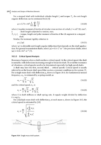
                       For a single mass shaft with deflection y shown in Figure 10.4, the fundamental natural
                                                        0
                       frequency,    , is estimated by a spring model, as
                                  n
                                  √     √
                                    k      g
                                =     =                                                  (10.22)
                              n
                                    m      y
                                            0
                       and the critical speed, n ,is
                                           c
                                    √
                                             √
                                 30   k    30   g
                             n =        =                                                (10.23)
                              c
                                      m        y
                                                0
                       where k is shaft stiffness or shaft spring rate. It equals weight divided by deflection
                       k = mg/y .
                               0
                         For a multiple mass shaft with deflection y at each mass w shown in Figure 10.5, the
                                                            i            i
                       critical speed is estimated by [10]
                                    √
                                    √
                                        z
                                    √ ∑
                                    √  g  w y
                                    √      i i
                             n =  30 √  i=1                                              (10.24)
                                    √
                              c        z
                                      √     2
                                    √ ∑
                                         w y
                                          i i
                                       i=1
                                        y 0
                                                  w i
                       Figure 10.4 Single mass shaft system.
   287   288   289   290   291   292   293   294   295   296   297