
Page 293 - Analysis and Design of Machine Elements
P. 293
y 1 y z Shafts 271
y i
w 1 w z
w 2 w j
w i
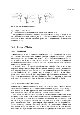
Figure 10.5 Multiple mass shaft system.
w –weightof ith mass, N;
i
y i – deflection of ith mass centre from centreline of rotation, mm.
A stepped shaft can be first partitioned into segments and placing its weight at the
segment centroid and then employing Eq. (10.24) to calculate the critical speed. Detailed
derivation of these equations for critical speeds can be found in books on mechanical
vibrations [3, 10].
10.4 Design of Shafts
10.4.1 Introduction
Shaft design aims to specify reasonable dimensions to ensure shafts satisfy operational
requirements. The design process has much interdependence on the design of mounted
elements, such as gears, bearings and so on. Therefore, shaft design must consider the
initial analysis and design of these elements simultaneously. Similar to the design of
other elements, shaft design involves the load carrying capacity analysis discussed pre-
viously and structural design.
Structural design is a flexible and complicated process and depends greatly on spe-
cific applications. It involves the specification of shaft geometries so that it is compatible
with mounted elements. Many factors, including mounting, locating and manufactur-
ing, need to be considered to ensure a secured location of each element and reliable
power transmission. Although there is no absolute rule for shaft structural design, the
following sections aim to provide general guidelines. Structural design is an important
task in shaft design, as it affects the performance, costs and assembly of shafts.
10.4.2 Materials and Heat Treatments
Considering the potential failure modes introduced in Section 10.2.5, candidate materi-
als for power transmission shafts should have good strength, especially fatigue strength,
high stiffness and, in some applications, good wear and corrosion resistance. Other fac-
tors, such as cost, weight and machinability, also need to be considered.
Most power transmission shafts are made of low- or medium-carbon steels, either
hot-rolled or cold-drawn. Low- or medium-carbon steels are commonly chosen as they
are at reasonable price, less sensitive to stress concentration and can be easily heat
treated. If higher strength is required, low alloy steels may be selected using appro-
priate heat treatment, such as quenching or tempering to achieve desired properties.
Surface hardening, including carburizing, nitriding and case hardening, can be used
to increase strength and wear resistance of shafts. For forged shafts, such as automo-
tive crankshafts, high-strength nodular cast iron is frequently selected because of shock