
Page 298 - Analysis and Design of Machine Elements
P. 298
Analysis and Design of Machine Elements
276
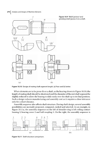
I Figure 10.9 Relief groove I and
II grinding-relief groove II on a shaft.
12.5 I II
3:1 3:1
1.6
(a) (b)
Figure 10.10 Design of mating shaft segment length. (a) Poor and (b) better.
When elements are to be press-fit on a shaft, as the bearing shown in Figure 10.10, the
length of mating shaft should be shortened and the diameter of the rest shaft segment be
slightly reduced to allow the bearing to slide easily over the shaft up to its final position.
Such a design reduces manufacturing and assembly cost as it requires a close tolerance
only for a short distance.
Assembly sequence also affects shaft structure. During shaft design, several assembly
possibilities are normally proposed, compared, ranked and selected. As an example, in
Figure 10.11a, the assembly sequence on the left of shoulder ring is left rolling contact
bearing 3, bearing cover 2 and half coupling 1. On the right, the assembly sequence is
1 2 3 4 5 6 7
(a) (b)
Figure 10.11 Shaft structure comparison.