
Page 299 - Analysis and Design of Machine Elements
P. 299
Shafts
gear 4, spacer 5, right rolling contact bearing 6 and bearing cover 7. The axial space 277
between bearing cover 2 and half coupling 1 is to provide access space for dismount-
ing bearing cover 2 to provide the bearing with lubricant. Figure 10.11b gives a similar
design, yet it requires a longer spacer.
10.4.6 Design Cases
Example Problem 10.1
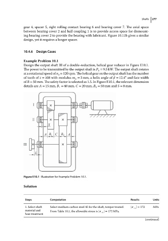
Design the output shaft III of a double-reduction, helical gear reducer in Figure E10.1.
The power to be transmitted by the output shaft is P = 9.5 kW. The output shaft rotates
3
at a rotational speed of n = 120 rpm. The helical gear on the output shaft has the number
3
∘
of teeth of z = 108 with modulus m = 3mm, a helix angle of = 12.4 and face width
n
of B = 50 mm. The safety factor is selected as 1.5. In Figure E10.1, the relevant dimension
details are A = 15 mm, B = 40 mm, C = 20 mm, B = 50 mm and S = 8 mm.
1 2
Figure E10.1 Illustration for Example Problem 10.1.
Solution
Steps Computation Results Units
1. Select shaft Select medium-carbon steel 45 for the shaft, temper treated. [ ] = 172 MPa
−1
material and From Table 10.1, the allowable stress is [ ] = 172 MPa.
−1
heat treatment
(continued)