
Page 295 - Analysis and Design of Machine Elements
P. 295
Shafts
4. Perform force analysis, stress analysis, rigidity analysis and critical speed analysis if 273
required.
5. Finalize structural design by modifying initial design if strength, rigidity and/or crit-
ical speed do not meet criteria; repeat previous steps if required.
6. Produce drawings.
10.4.5 Structural Design of Shafts
Structural design determines the shape and dimensions of a stepped shaft. Geometri-
cal variations in a shaft, such as shoulders, grooves and keyseats, rely on the layout of
mounted elements. An ideal shaft design should facilitate manufacturing and assembly,
as well as location of mating elements. Sufficient strength and rigidity should be guar-
anteed in shaft design. The following issues greatly affect shaft structure and need to be
addressed during the structural design process.
10.4.5.1 Measures to Increase Shaft Strength and Rigidity
The layout of shaft mating elements, for example, gears and bearings, must be specified
in the early design stage to facilitate producing torque and bending moment diagrams.
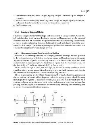
Appropriate layout of power transmitting elements could reduce the loads on a shaft
and ultimately increase strength. As illustrated in Figure 10.6, the maximum torque on
the shaft is T + T in Figure 10.6a, while T in Figure 10.6b.
1 2 1
Shafts should be kept as short, stiff and light, as possible. Bearings are better placed
on either side of power transmitting elements to provide stable supports and close to
the power transmitting elements to minimize bending moments.
Stress concentration greatly affects fatigue strength of shaft. Therefore, geometrical
discontinuities, such as shoulders, keyseats and retaining ring grooves, should be away
from high stress regions. If this is not possible, use generous radii for fillets and relief
grooves and good surface finishes. Local surface enhancement processes, such as shot
peening, cold rolling or heat treatment, like carburizing, nitriding, case hardening and
so on, are recommended for these regions.
Input Input
3 2 3 1
2 1
T 1 T 3 T 1
T 3
T 2 T 2
Figure 10.6 Layouts of power transmitting elements on shafts. (a) Poor and (b) good.