
Page 296 - Analysis and Design of Machine Elements
P. 296
Analysis and Design of Machine Elements
274
10.4.5.2 Locating and Fastening Elements on a Shaft
To prevent relative movement between elements and a shaft, each element must be
located accurately on the shaft, both axially and circumferentially and securely held in
position during operation to ensure reliable power transmission.
(1) Axially locating and fastening elements on a shaft
Elements must be held in position along shafts, especially for thrust loads produc-
ing elements, such as helical or bevel gears, or tapered roller bearings. Accurate axial
positioning of gears or bearings requires a shoulder, spacer, locknut and lockwasher,
retaining ring, collar and screw, tapered surface and so on.
A shoulder is a change in the shaft diameter against which to locate an element car-
rying large thrust loads. The use of shaft shoulders is a simple, convenient and reli-
able method for axially locating elements in a stepped shaft. Shoulders include locating
shoulders and non-locating shoulders.
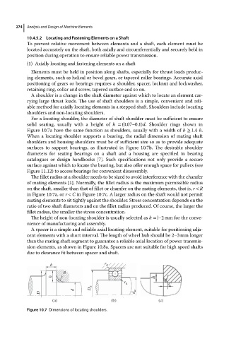
For a locating shoulder, the diameter of shaft shoulder must be sufficient to ensure
solid seating, usually with a height of h = (0.07–0.1)d. Shoulder rings shown in
Figure 10.7a have the same function as shoulders, usually with a width of b ≥ 1.4 h.
When a locating shoulder supports a bearing, the radial dimension of mating shaft
shoulders and housing shoulders must be of sufficient size so as to provide adequate
surfaces to support bearings, as illustrated in Figure 10.7b. The desirable shoulder
diameters for seating bearings on a shaft and a housing are specified in bearing
catalogues or design handbooks [7]. Such specifications not only provide a secure
surface against which to locate the bearing, but also offer enough space for pullers (see
Figure 11.12) to access bearings for convenient disassembly.
The fillet radius at a shoulder needs to be sized to avoid interference with the chamfer
of mating elements [1]. Normally, the fillet radius is the maximum permissible radius
on the shaft, smaller than that of fillet or chamfer on the mating elements, that is, r < R
in Figure 10.7a, or r < C in Figure 10.7c. A larger radius on the shaft would not permit
mating elements to sit tightly against the shoulder. Stress concentration depends on the
ratio of two shaft diameters and on the fillet radius produced. Of course, the larger the
fillet radius, the smaller the stress concentration.
The height of non-locating shoulder is usually selected as h = l–2 mm for the conve-
nience of manufacturing and assembly.
A spacer is a simple and reliable axial locating element, suitable for positioning adja-
cent elements with a short interval. The length of wheel hub should be 2–3 mm longer
than the mating shaft segment to guarantee a reliable axial location of power transmis-
sion elements, as shown in Figure 10.8a. Spacers are not suitable for high speed shafts
due to clearance fit between spacer and shaft.
b r a
R
h r
r a
D a
d
D d a
(a) (b) (c)
Figure 10.7 Dimensions of locating shoulders.