
Page 416 - Analysis and Design of Machine Elements
P. 416
394
Analysis and Design of Machine Elements
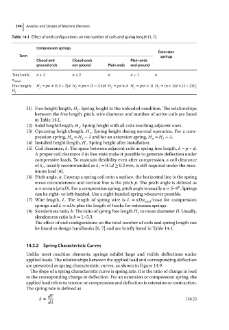
Table 14.1 Effect of end configurations on the number of coils and spring length [1, 7].
Compression springs
Extension
Term springs
Closed and Closed ends Plain ends
ground ends not ground Plain ends and ground
Total coils, n + 2 n + 2 n n + 1 n
n
totoal
Free length, H = pn + (1.5 ∼ 2)dH = pn + (3 ∼ 3.5)dH = pn + dH = p(n + 1) H = (n + 1)d + (1 ∼ 2)D
f f f f f i
H f
11) Free height/length, H . Spring height in the unloaded condition. The relationships
f
between the free length, pitch, wire diameter and number of active coils are listed
in Table 14.1.
12) Solid height/length, H . Spring height with all coils touching adjacent ones.
s
13) Operating height/length, H . Spring height during normal operation. For a com-
o
pression spring, H = H − and for an extension spring, H = H + .
f
o
o
f
14) Installed height/length, H . Spring height after installation.
i
15) Coil clearance, . The space between adjacent coils at spring free length, = p − d.
Apropercoilclearance in free state make it possible to generate deflection under
compressive loads. To maintain flexibility even after compression, a coil clearance
of , usually recommended as = 0.1d ≥ 0.2 mm, is still required under the max-
1 1
imum load [4].
16) Pitch angle, . Unwrap a spring coil onto a surface, the horizontal line is the spring
mean circumference and vertical line is the pitch p. The pitch angle is defined as
∘
= arctan (p/ D). For a compression spring, pitch angle is usually = 5–9 .Springs
can be right- or left-handed. Use a right-handed spring whenever possible.
17) Wire length, L. The length of spring wire is L = Dn /cos for compression
total
springs and L = Dn plus the length of hooks for extension springs.
18) Slenderness ratio, b. The ratio of spring free length H to mean diameter D. Usually,
f
slenderness ratio is b = 1–5.3.
The effect of end configurations on the total number of coils and spring length can
be found in design handbooks [6, 7] and are briefly listed in Table 14.1.
14.2.2 Spring Characteristic Curves
Unlike most machine elements, springs exhibit large and visible deflections under
applied loads. The relationships between the applied load and corresponding deflection
are presented as spring characteristic curves, as shown in Figure 14.9.
The slope of a spring characteristic curve is spring rate. It is the ratio of change in load
to the corresponding change in deflection. For an extension or compression spring, the
applied load refers to tension or compression and deflection is extension or contraction.
The spring rate is defined as
dF
k = (14.1)
d 