
Page 385 - Analysis, Synthesis and Design of Chemical Processes, Third Edition
P. 385
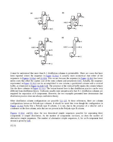
It must be understood that more than N–1 distillation columns is permissible. There are cases that have
                    been  reported  where  the  sequence  in Figure  12.1(c)  is  actually  more  economical  than  either  of  the
                    sequences in Figures 12.1(a) and 12.1(b). This occurs because the sequence in Figure 12.1(c) has lower
                    utility costs that offset the capital cost of the extra column and peripherals [10]. Actually, the sequence
                    represented  in Figure 12.1(c) can be accomplished in one column, a partitioned column with a vertical
                    baffle, as illustrated in Figure 12.1(d) [10]. The presence of the vertical baffle makes the column behave

                    like the three columns in Figure 12.1(c). The lesson learned here is that distillation practice can be very
                    different from distillation theory. Textbooks usually state unequivocally that N–1 distillation columns are
                    required  for  separation  of N components. However, the two examples presented here demonstrate that
                    distillation practice does not always conform to theory.


                    Other  distillation  column  configurations  are  possible  [11–13].  In  these  references,  there  are  column
                    configurations known as Petlyuk-type columns. It should be noted that even though the configuration in
                    Figure  12.1(c)  looks  like  a  Petlyuk–type  II  column,  it  is  not,  due  to  the  presence  of  a  reboiler  and  a
                    condenser on the first column, units that are not present in the Petlyuk–type II column.


                    Figures  12.1(a)  and (b)  show  the  two  theoretical  simple  sequences  possible  for  separating  three
                    components  in  simple  distillation.  As  the  number  of  components  increases,  so  does  the  number  of
                    alternative simple sequences. The number of alternative simple sequences, S,  for  an N-component  feed
                    stream is given by [14].


                    (12.1)