
Page 388 - Analysis, Synthesis and Design of Chemical Processes, Third Edition
P. 388
2. If the azeotrope is a binary, heterogeneous azeotrope, that means there is a region where the two
components form two mutually immiscible liquid phases (both in equilibrium with the
azeotropic vapor composition, which is between the two liquid compositions), and hence a
phase separator and a second column are added. The phase separator provides one phase on the
other side of the azeotrope from the feed, so that phase can be purified by distillation in a
second column (Figure 12.4[b]).
3. If the azeotrope concentration is pressure sensitive, one column is used to distill close to the
azeotrope. One “pure” component is produced from the bottom of this first column. Then the
pressure of the distillate is raised so that the azeotropic composition is now below the distillate
composition. Then a second column is used to purify the second component. Because the
volatility switches as the azeotrope is crossed, the second component is in the bottom stream of
the second column (Figure 12.4[c]). This particular sequence assumes that the azeotrope is less
concentrated in A at higher pressures.
4. A third component can be added to change the phase behavior. This method is discussed in the
next section.
The first alternative is illustrated in Figure 12.4(a). Here, a distillation column is used that will provide
“pure” B in the bottoms and a near-azeotropic mixture in the distillate. The McCabe-Thiele construction
for this distillation column is illustrated in Figure 12.5(a). Then a different type of separation is used to
purify Component A (not shown on the McCabe-Thiele diagram). The impure stream from the second
separator should be recycled, if possible; however, treatment as a waste stream is also possible. The
recycle stream will most likely be fed to a different tray from the feed stream, because distillation column
feeds should always be near the point in the column with the same concentration as the feed stream.
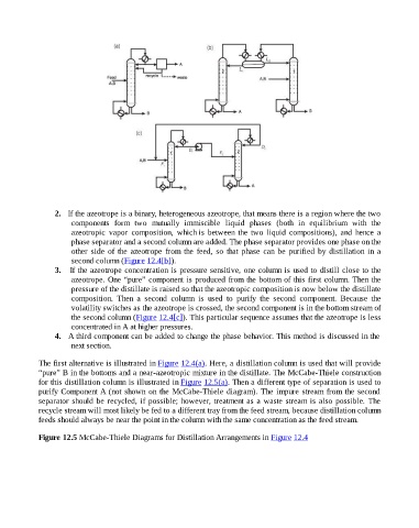
Figure 12.5 McCabe-Thiele Diagrams for Distillation Arrangements in Figure 12.4