
Page 393 - Analysis, Synthesis and Design of Chemical Processes, Third Edition
P. 393
increases with time. The residue curves represent this fact with an arrow in the direction of increasing
temperature. It is also true that residue curves never cross. Points on the residue curve map are defined as
follows:
Stable node: Arrows on all curves point toward this point (highest temperature).
Unstable node: Arrows on all curves point away from this point (lowest temperature).
Saddle point: Arrows point both toward and away from this point (intermediate temperature).
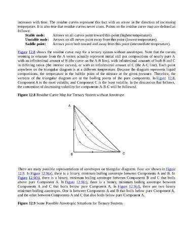
Figure 12.8 shows the residue curve map for a ternary system without azeotropes. Note that the curves
seeming to emanate from the A vertex actually represent initial still pot compositions of nearly pure A
with an infinitesimal amount of B (the curve on the A-B line), with infinitesimal amounts of both B and C
in differing ratios (the interior curves), or with an infinitesimal amount of C (the A-C line). Each point
anywhere on the triangular diagram is at a different temperature. Because the diagram represents liquid
compositions, the temperature is the bubble point of the mixture at the given pressure. Therefore, the
vertices of the triangular diagram are at the boiling points of the pure components. In Figure 12.8,
Component A is the most volatile, and Component C is the least volatile. In the discussion that follows,
the convention of decreasing volatility for components A-B-C will be followed.
Figure 12.8 Residue Curve Map for Ternary System without Azeotrope
There are many possible representations of azeotropes on triangular diagrams. Four are shown in Figure
12.9. In Figure 12.9(a), there is a binary, minimum boiling azeotrope between Components A and B. In
Figure 12.9(b), there is a binary, minimum boiling azeotrope between Components B and C that boils
above pure Component A. In Figure 12.9(c), there is a binary, minimum boiling azeotrope between
Components A and C that boils below pure Component A. In Figure 12.9(d), there are two binary
minimum boiling azeotropes. One is between Components A and B that boils below pure Component A,
and the other between Components A and C that also boils below pure Component A.
Figure 12.9 Some Possible Azeotropic Situations for Ternary Systems