Page 335 - Applied Process Design For Chemical And Petrochemical Plants Volume III
P. 335

66131_Ludwig_CH11A  5/30/2001 4:49 PM  Page 294


                       294                       Applied Process Design for Chemical and Petrochemical Plants

                                   Tons* of
                         No. of     Refrig.                                   Approximate Dimensions
                        Boosters    at 50°F        A              B             C              D           E*            F
                           1          30         5 ft-0 in.    16 ft-0 in.   14 ft-0 in.    2 ft-6 in.   5 ft-3 in.    4 ft-0 in.
                           1          40         5 ft-6 in.    17 ft-0 in.   14 ft-0 in.    2 ft-10 in.  5 ft-3 in.    4 ft-0 in.
                           1          50         6 ft-0 in.    18 ft-0 in.   14 ft-6 in.    3 ft-0 in.   5 ft-3 in.    4 ft-0 in.
                           2          60          12 ft        12 ft-0 in.   14 ft-0 in.    4 ft-6 in.   5 ft-3 in.    4 ft-0 in.
                           2          80          13 ft        13 ft-6 in.   14 ft-0 in.    5 ft-0 in.   5 ft-3 in.    4 ft-0 in.
                           2         100          15 ft        14 ft-0 in.   15 ft-6 in.    5 ft-6 in.   6 ft-3 in.    5 ft-0 in.
                           2         125          15 ft        15 ft-0 in.   16 ft-0 in.    6 ft-0 in.   6 ft-3 in.    5 ft-0 in.
                           2         160          15 ft        17 ft-0 in.   16 ft-0 in.    7 ft-0 in.   6 ft-3 in.    5 ft-0 in.
                           3         200          16 ft        16 ft-0 in.   16 ft-0 in.    9 ft-0 in.   6 ft-3 in.    5 ft-0 in.
                           3         250          16 ft        17 ft-6 in.   17 ft-0 in.    10 ft-0 in.  6 ft-9 in.    5 ft-6 in.
                           4         320          18 ft        18 ft-0 in.   17 ft-0 in.    13 ft-0 in.  6 ft-9 in.    5 ft-6 in.
                           4         400          20 ft        20 ft-0 in.   18 ft-0 in.    15 ft-0 in.  7 ft-9 in.    6 ft-6 in.
                       *See Figure 11-7 for estimating capacities at other temperatures.


                                                                                                          † †


                                                                    †


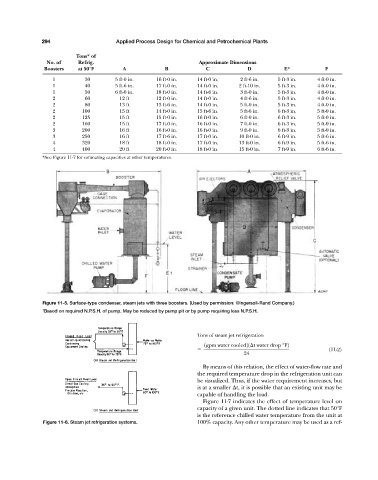
                       Figure 11-5. Surface-type condenser, steam jets with three boosters. (Used by permission: ©Ingersoll-Rand Company.)
                       † Based on required N.P.S.H. of pump. May be reduced by pump pit or by pump requiring less N.P.S.H.


                                                                             Tons of steam jet refrigeration
                                                                                1gpm water cooled21 t water drop °F2
                                                                                                                           (11-2)
                                                                                             24

                                                                               By means of this relation, the effect of water-flow rate and
                                                                             the required temperature drop in the refrigeration unit can
                                                                             be visualized. Thus, if the water requirement increases, but
                                                                             is at a smaller  t, it is possible that an existing unit may be
                                                                             capable of handling the load.
                                                                               Figure 11-7 indicates the effect of temperature level on
                                                                             capacity of a given unit. The dotted line indicates that 50°F
                                                                             is the reference chilled water temperature from the unit at
                       Figure 11-6. Steam jet refrigeration systems.         100% capacity. Any other temperature may be used as a ref-
   330   331   332   333   334   335   336   337   338   339   340