
Page 142 - Applied Petroleum Geomechanics
P. 142
Basic rock fracture mechanics 135
σ max
a
Stress
2a
ρ t σ L
2a
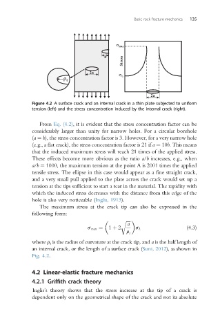
Figure 4.2 A surface crack and an internal crack in a thin plate subjected to uniform
tension (left) and the stress concentration induced by the internal crack (right).
From Eq. (4.2), it is evident that the stress concentration factor can be
considerably larger than unity for narrow holes. For a circular borehole
(a ¼ b), the stress concentration factor is 3. However, for a very narrow hole
(e.g., a flat crack), the stress concentration factor is 21 if a ¼ 10b. This means
that the induced maximum stress will reach 21 times of the applied stress.
These effects become more obvious as the ratio a/b increases, e.g., when
a/b ¼ 1000, the maximum tension at the point A is 2001 times the applied
tensile stress. The ellipse in this case would appear as a fine straight crack,
and a very small pull applied to the plate across the crack would set up a
tension at the tips sufficient to start a tear in the material. The rapidity with
which the induced stress decreases with the distance from this edge of the
hole is also very noticeable (Inglis, 1913).
The maximum stress at the crack tip can also be expressed in the
following form:
a
ffiffiffiffi
r
s max ¼ 1 þ 2 s L (4.3)
r t
where r t is the radius of curvature at the crack tip, and a is the half length of
an internal crack, or the length of a surface crack (Suni, 2012), as shown in
Fig. 4.2.
4.2 Linear-elastic fracture mechanics
4.2.1 Griffith crack theory
Inglis’s theory shows that the stress increase at the tip of a crack is
dependent only on the geometrical shape of the crack and not its absolute