
Page 145 - Applied Petroleum Geomechanics
P. 145
138 Applied Petroleum Geomechanics
in the material begins to grow. If the stress intensity factor of a fracture is
equal or greater than its critical stress intensity factor or toughness, then the
fracture starts to grow or be unstable, as shown in the following equation
for Mode I fractures.
p ffiffiffiffiffi
K ¼s pa K IC (4.8)
I
where K IC is the fracture toughness of Mode I fracture.
4.2.3 Three basic fracture modes
Different loading configurations at the crack tips lead to different modes of
crack tip surface displacements. Three single loading configurations form
three basic fracture modes, i.e., mode I, mode II, and mode III, as illustrated
in the following (Fig. 4.3):
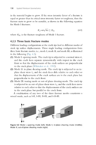
(1) Mode I: opening mode. The crack tip is subjected to a normal stress s,
and the crack faces separate symmetrically with respect to the crack
front so that the displacements of the crack surfaces are perpendicular
to the crack plane (Whittaker et al., 1992).
(2) Mode II: in-plane shearing mode. The crack tip is subjected to an in-
plane shear stress s i , and the crack faces slide relative to each other so
that the displacements of the crack surfaces are in the crack plane but
perpendicular to the crack front.
(3) Mode III: tearing mode or out-of-plane shearing mode. The crack tip
is subjected to an out-of-plane shear stress s 0 , and the crack faces move
relative to each other so that the displacements of the crack surfaces are
in the crack plane but parallel to the crack front.
A combination of any two of the three fracture modes constitutes a
mixed mode, such as I-II, I-III, II-III, and I-II-III.
Figure 4.3 Mode I, opening mode (left); Mode II, in-plane shearing mode (middle);
Mode III, out-of-plane shearing mode (right).