
Page 148 - Applied Petroleum Geomechanics
P. 148
Basic rock fracture mechanics 141
y
τ i
σ y
τ xy
σ x
r τ i
τ i B O A θ x
2a
τ i
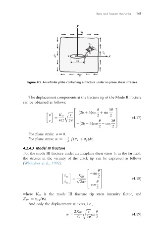
Figure 4.5 An infinite plate containing a fracture under in-plane shear stresses.
The displacement components at the fracture tip of the Mode II fracture
can be obtained as follows:
q 3q
2 3
u K II r 6 2 2 7
r ffiffiffiffiffiffi ð2k þ 3Þsin þ sin
¼ 6 7 (4.17)
v 4G 2p 4 q 3q 5
ð2k 3Þcos cos
2 2
For plane strain: w ¼ 0.
n R
For plane stress: w ¼ E ðs x þ s y Þdz.
4.2.4.3 Model III fracture
For the mode III fracture under an antiplane shear stress s 0 in the far field,
the stresses in the vicinity of the crack tip can be expressed as follows
(Whittaker et al., 1992):
q
2 3
sin
s xz K III 6 2 7
¼ p ffiffiffiffiffiffiffi 6 7 (4.18)
s yz 2pr 4 q 5
cos
2
where K III is the mode III fracture tip stress intensity factor, and
p ffiffiffiffiffi
K III ¼ s 0 pa.
And only the displacement w exists, i.e.,
r ffiffiffiffiffiffi
2K III r q
w ¼ sin (4.19)
G 2p 2