
Page 150 - Applied Petroleum Geomechanics
P. 150
Basic rock fracture mechanics 143
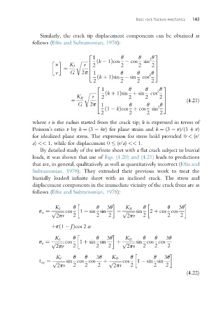
Similarly, the crack tip displacement components can be obtained as
follows (Eftis and Subramonian, 1978):
2 3
1 q q 2 q
u K I r 6 2 2 2 2 7
r ffiffiffiffiffiffi ðk 1Þcos cos sin
¼ 6 7
v G 2p 1 q q q 5
4
ðk þ 1Þsin sin cos 2
2 2 2 2
1 q q 2 q
2 3
ðk þ 1Þsin þ sin cos
r ffiffiffiffiffiffi
K II r 6 2 2 2 2 7
þ 6 7 (4.21)
G 2p 1 q q q 5
4
ð1 kÞcos þ cos sin 2
2 2 2 2
where r is the radius started from the crack tip; k is expressed in terms of
Poisson’s ratio n by k ¼ (3 4n) for plane strain and k ¼ (3 n)/(1 þ n)
for idealized plane stress. The expression for stress hold provided 0 < (r/
a) << 1, while for displacement 0 (r/a) << 1.
By detailed study of the infinite sheet with a flat crack subject to biaxial
loads, it was shown that use of Eqs. (4.20) and (4.21) leads to predictions
that are, in general, qualitatively as well as quantitatively incorrect (Eftis and
Subramonian, 1978). They extended their previous work to treat the
biaxially loaded infinite sheet with an inclined crack. The stress and
displacement components in the immediate vicinity of the crack front are as
follows (Eftis and Subramonian, 1978):
K I q q 3q K II q q 3q
s x ¼ p ffiffiffiffiffiffiffi cos 1 sin sin p ffiffiffiffiffiffiffi sin 2 þ cos cos
2pr 2 2 2 2pr 2 2 2
þsð1 JÞcos 2 a
K I q q 3q K II q q 3q
s y ¼ p ffiffiffiffiffiffiffi cos 1 þ sin sin þ p ffiffiffiffiffiffiffi sin cos cos
2pr 2 2 2 2pr 2 2 2
K I q q 3q K II q q 3q
s xy ¼ p ffiffiffiffiffiffiffi sin cos cos þ p ffiffiffiffiffiffiffi cos 1 sin sin
2pr 2 2 2 2pr 2 2 2
(4.22)