
Page 146 - Applied Petroleum Geomechanics
P. 146
Basic rock fracture mechanics 139
y
σ
σ y
τ xy
σ x
r σ
σ B O θ x
A
2a
σ
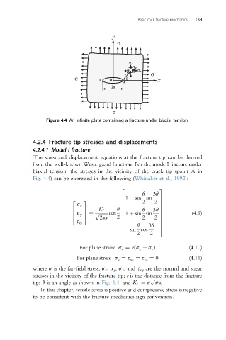
Figure 4.4 An infinite plate containing a fracture under biaxial tension.
4.2.4 Fracture tip stresses and displacements
4.2.4.1 Model I fracture
The stress and displacement equations at the fracture tip can be derived
from the well-known Westergaard function. For the mode I fracture under
biaxial tension, the stresses in the vicinity of the crack tip (point A in
Fig. 4.4) can be expressed in the following (Whittaker et al., 1992):
2 3
q 3q
6 1 sin sin
2 3 2 7
6 2 7
s x
6 7
K I q 3q 7
6 7 q 6
4 s y 5 ¼ p ffiffiffiffiffiffiffi cos 6 1 þ sin sin 7 (4.9)
2pr 2 6 2 7
6 2 7
s xy
q
6 7
sin cos
4 3q 5
2 2
For plane strain: s z ¼ nðs x þ s y Þ (4.10)
For plane stress: s z ¼ s xz ¼ s yz ¼ 0 (4.11)
where s is the far-field stress; s x , s y , s z , and s xy are the normal and shear
stresses in the vicinity of the fracture tip; r is the distance from the fracture
p ffiffiffiffiffi
tip; q is an angle as shown in Fig. 4.4; and K I ¼ s pa.
In this chapter, tensile stress is positive and compressive stress is negative
to be consistent with the fracture mechanics sign convention.