
Page 18 - Applied Petroleum Geomechanics
P. 18
8 Applied Petroleum Geomechanics
The near-field stresses are the stress redistributions of the in situ stresses
caused by current excavations, such as the stresses near the borehole wall
in Fig. 1.6.
1.2 Mohr’s circle representation of stresses
1.2.1 Mohr’s circles for two-dimensional stresses
Mohr’s circle or the Mohr diagram is a useful tool to represent the stress
state and rock failure. The Mohr circle can be used to determine graphically
the stress components acting on a rotated coordinate system, i.e., acting on
a differently oriented plane passing through a particular point (e.g., the
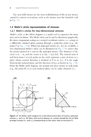
point P in Fig. 1.7A). When the principal stresses (s 1 , s 3 ) are available, a
two-dimensional Mohr’s circle can be illustrated in Fig. 1.7A; notice that
the stresses plotted in x-axis are the principal stresses. The diameter of the
circle is s 1 s 3 and the center is at ((s 1 þ s 3 )/2,0). The normal stress s
and shear stress s at each point on the circle represent a state of stress on a
plane whose normal direction is inclined at q to s 1 (i.e., q is the angle
between the inclined plane and the direction of s 3 ), as shown in Fig. 1.7B.
From the Mohr circle diagram, the normal and shear stresses at each point
(e.g., the point P) or in each inclined plane can be easily obtained, i.e.,
(A) (B)
τ
1 σ − 3 σ σ 1 − σ 3 cos θ 2 y
2 2
P (σ ,τ ) θ
σ
τ
o 2θ
0 σ 3 σ σ 1 σ σ 1 τ
1 σ + 3 σ θ
2 x
σ
σ 1 + σ 3 + σ 1 − σ 3 cos θ 2 σ
2 2 3
Figure 1.7 (A) Mohr’s circle diagram for a two-dimensional state of stresses (principal
stresses s 1 and s 3 ). (B) Shear and normal stresses on a plane exerted by the far-field
principal stresses (s 1 and s 3 ) (corresponding to the stress state at the point P).