Page 19 - Applied Petroleum Geomechanics
P. 19

Stresses and strains  9


                                     s 1 þ s 3  s 1   s 3
                                 s ¼        þ        cos 2q
                                        2        2
                                                                         (1.12)
                                     s 1   s 3
                                 s ¼        sin 2q
                                        2
                 Eqs. (1.12) and (1.5) are also very useful for analyzing stress states in
              fractures. The maximum shear stress can be obtained from Eq. (1.12) when
              2q ¼ 90 degrees, that is,

                                              s 1   s 3
                                       s max ¼                           (1.13)
                                                2
              1.2.2 Mohr’s circles for three-dimensional stresses

              To construct Mohr’s circles for a three-dimensional case of stresses at a
              point, the values of the principal stresses (s 1 , s 2 , s 3 ) and their principal
              directions (n 1 , n 2 , n 3 ) must be first evaluated. When the principal stresses
              are available, the three-dimensional Mohr’s circles can be plotted (Parry,
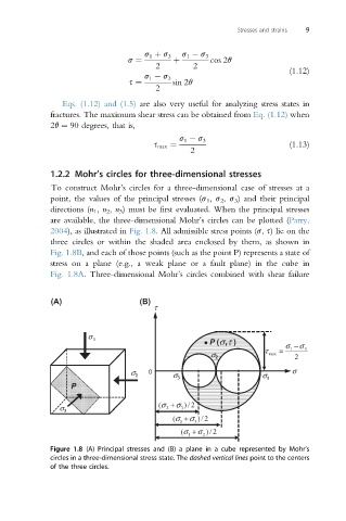
              2004), as illustrated in Fig. 1.8. All admissible stress points (s, s) lie on the
              three circles or within the shaded area enclosed by them, as shown in
              Fig. 1.8B, and each of those points (such as the point P) represents a state of
              stress on a plane (e.g., a weak plane or a fault plane) in the cube in
              Fig. 1.8A. Three-dimensional Mohr’s circles combined with shear failure


              (A)                   (B)
                                       τ


                       σ 1                           P (σ ,τ )
                                                                   τ   =  σ − σ 3
                                                                         1
                                                      σ 2           max   2
                                  σ 2  0    σ 3        σ 2        σ 1     σ
                   P


                σ 3                     (σ + σ 3  2 / )
                                          2
                                            (σ + σ 3  2 / )
                                              1
                                              (σ + σ 2  2 / )
                                                1
              Figure 1.8 (A) Principal stresses and (B) a plane in a cube represented by Mohr’s
              circles in a three-dimensional stress state. The dashed vertical lines point to the centers
              of the three circles.
   14   15   16   17   18   19   20   21   22   23   24