
Page 127 - Applied Process Design For Chemical And Petrochemical Plants Volume II
P. 127
116 Applied Process Design for Chemical and Petrochemical Plants
The non-key components are computed and tabu-
1.661 (2.669) + .25 - 0.5 = 1.664
A, = lated in Column 7 of Table 8-10.
The stripping factor, S,, is taken as 1/A, = 0.6010 7. Third Iteration.
4. Calculation of required number of theoretical stages. A third iteration gave (Lo)min = 1,063.73, Lo =
Using Equation &216 for n-butane, 1,914.72, L, = 2,087.8, and V1 = 1,801.92, with no
change in the calculated off gas component flows.
( 0.601"" - 0.601) 4.0+ [ 1- , 1.664"" - 1.66411 33 The stripping calculations are handled in a man-
3.36 = \ 0.601"+1 - 1 1.664"'l- 1 ner similar to the steps above, and using the figures
indicated.
which is equivalent to Intercooling for Absorbers
1 0.601-1 )4.0+ [ 1.664- 1 11 33.6
3.36~ 1- Most absorbers require some intercooling between
0.601"+' - 1
1.664"" - 1
some stages or trays to remove heat of absorption and to
Solving for n by trial and error yields, n = 5.12 provide internal conditions compatible with proper or
5. Calculation of absorption of non-keys. required absorption. Some temperature rise (10-30°F) is
usually designed into the initial conditions. The rise above
Equation 8-217 is used with n = 5.12 to calculate vi,
as for example, for i-butane, this must be handled with intercoolers.
The total intercooler duty is the difference between the
AT = 1.233 total heat in of the rich gas and lean oil and the total heat
AB = 1.227 out of the off gas and rich oil all at the terminal calculat-
ed or design conditions. The total duty is often divided
A, = J1.227 (2.333) + 0.25 - 0.5 = 1.229
between several coolers placed to re-cool the oil as it pass-
es down the column. If intercoolers are not used, then the
s, =- =OM37
1.229 absorption cannot meet the design terminal outlet condi-
V, = 17.8 tions and the quantity of material absorbed will be
1, = (0.001) (2,005.7) = 2.01 reduced. If the intercooling is too great so as to subcool,
then greater absorption may be achieved, but this can be
controlled by the intercooler operation.
A second approach to the same result involves the same
requirements as for a balanced "heat" design; the heat of
1, = 17.8 + 2.01 - 3.10 = 16.71 absorption of the actual components absorbed must equal
The remaining non-keys in the off-gas are calculated the sum of the heat added to the lean oil and to the lean
in a similar manner and are tabulated in Column 6 of
Table 8-10. Note that the calculated values are some
what different from the assumed values in Column 5.
6. Second Iteration.
Using the previous calculated values, the net amount
absorbed is 1,975 - 1,799.59 = 175.41 mols/hr. The
minimum rate of lean oil is calculated from
from which (Lo)min = 1,061.2 mols/hr and
Lo = 1.8 (1,061.2) = 1,910.2 mols/hr
An overall material balance gives L, = 2,085.6. The
effective absorption factor for n-C4 is A, = 1.627, and
S, = 0.6145, n is calculated from
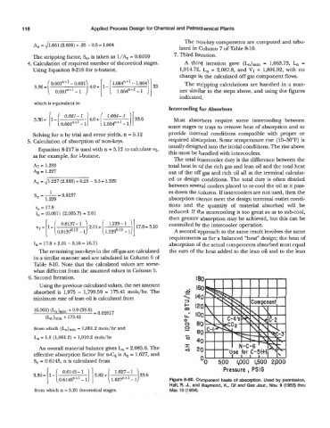
Pressure, PSlG
Figure 8-60. Component heats of absorption. Used by permission,
Hall, R. J., and Raymond, K., Oil and Gas Jour., Nov. 9 (1953) thru
from which n = 5.20 theoretical stages. Mar. 15 (1 954).