
Page 186 - Applied Process Design For Chemical And Petrochemical Plants Volume II
P. 186
Distillation 175
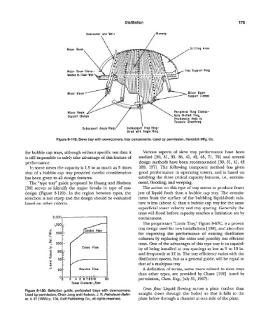
Downcomer and Weir /Monwoy
\
,Stilling Area
/Troy Support Ring
Welded to Tower Wall
Minor Beom
Support Clamps
Minor Beam
\Note
Support Clamps /\ Slotted Tri
Frictionolly Helt IU
Promote Breathing.
Subsupport Angle Ring Subsupport Tray Ring-
Used with Angle Ring.
Flgure 8-119. Sieve tray with downcomers, tray components. Used by permission, Hendrick Mfg. Co.
for bubble cap trays, although without specific test data it Various aspects of sieve tray performance have been
is still impossible to safely take advantage of this feature of studied [30, 31, 33, 36, 41, 42, 45, 71, 781 and several
performance. design methods have been recommended [30, 31,41,42
In some sieves the capacity is 1.5 to as much as 3 times 189, 1971. The following composite method has given
that of a bubble cap tray provided careful consideration good performance in operating towers, and is based on
has been given to all design features. satisfjmg the three critical capacity features, i.e., entrain-
The “type tray” guide proposed by Huang and Hodson ment, flooding, and weeping.
E301 serves to identify the major breaks in type of tray The action on this type of tray seems to produce fewer
design (Figure 8-120). In the region between types, the jets of liquid froth than a bubble cap tray. The entrain-
selection is not sharp and the design should be evaluated ment from the surface of the bubbling liquid-froth mix-
based on other criteria. ture is less (about %) than a bubble cap tray for the same
superficial tower velocity and tray spacing. Generally the
trays will flood before capacity reaches a limitation set by
21000f-----l entrainment.
The proprietary “Linde Tray,” Figure 8-67C, is a proven
tray design used for new installations [ 1981, and also often
i
f 500 for improving the performance of existing distillation
\ columns by replacing the older and possibly less efficient
0
trays. One of the advantages of this type tray is its capabil-
.- Cross Flow ity of being installed at tray spacings as low as 9 to 10 in.
a and frequently at 12 in. The tray efficiency varies with the
O” 50 distillation system, but as a general guide, will be equal to
.- that of a multipass tray.
a
-1 20 Reverse Flow A definition of terms, some more related to sieve trays
than other types, are provided by Chase [192] (used by
permission, C k Eng., July 31, 1967):
Tower Diameter ,Feet
Crossflow: Liquid flowing across a plate (rather than
Figure 8120. Selection guide, perforated trays with downcomers.
Used by permission, Chen-Jung and Hodson, J. R. Petroleum Reffn- straight down through the holes) so that it falls to the
er, V. 37 (1958) p. 104, Gulf Publishing Co., all rights reserved. plate below through a channel at one side of the plate.