
Page 189 - Applied Process Design For Chemical And Petrochemical Plants Volume II
P. 189
1 7% Applied Process Design for Chemical and Petrochemical Plants
:irculation
Zone
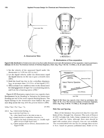
a. Mechanism 1.
etrograde
Flow
A. Downcomer Weir. b. Mechanism 2.
B. Mechanisms of flow separation.
Figure 8122. Modification of downcomer weir at tray floor outlet; (A) downcomer weir; (6) mechanism of flow separation. Used by permission,
Biddulph, M. W. et al. The American Institute of Chemical Engineers, Cbern. Eng. Prog. V 89. No. 12 (1993), p. 56, all rights resewed.
1. Set the velocity of the unaerated liquid under the
downcomer to 1.6 ft/sec (0.5 m/sec).
2. Let the liquid velocity under the downcomer equal
the liquid velocity on the tray to give a smooth entry
[2371. owncomer Flood
3. Hold the head loss due to the underflow clearance,
hudc, to no more than 1.0-1.5 in. of hot liquid [117].
4. Allow at least 3 sec residence time in the downcomer
for disengagement of vapor for a nonfoaming system,
and 6 sec for a foaming system [238] .”
Figure 8-123 illustrates a typical sieve tray capacity chart.
Entrainment by jet flooding or limitation by downcomer Liquid Rate *
flooding are two of the main capacity limiting factors. The
liquid backup in the downcomer must balance the pres- Figure 8-123. Sieve tray capacity chart. Used by permission, Bid-
sure drop across the tray, with the process balance [209]. dulph, M. W., et al. The American Institute of Chemical Engineers,
Chem. Eng. Prog. V. 89 No. 12 (1 993), p. 56, all rights resewed.
adhfd = hw + hli + hudc - h, (8-253)
Hole Size and Spacing
where hfd = downcomer backup, in.
hw =wet tray head loss, in. Most of the literature has presented data for trays with
hli = clear liquid head at the inlet to tray, in. holes of ?&in. through %-in. diameter. The work of Hunt et
hudc = head loss due to underflow clearance, in. al. [33] includes Kin. holes. Some commercial units have
h, = head in the back of downcomer, in. (usually negli- used K and 1-in. holes, although these sizes should be
gible except at high liquid load) used with caution when adequate data are not available.
ad = mean aeration factor of froth, dimensionless (see The recommended hole size for the average clean service
Figure 8-126) is %-in. based on present published data. Holes of %in.