
Page 192 - Applied Process Design For Chemical And Petrochemical Plants Volume II
P. 192
Distillation 181
Dry Tray Pressure Drop hole, condition or design of the “lip” of the hole, and
some other less prominent variables. The correlation for
This is the drop occurring when the vapor passes this concept for the orifice discharge coefficient is from
through the holes on the tray. The relation below [25] cor- Liebson, et al. [42], see Figure 8-129. Use C, from this fig-
relates the data of several of the major investigators with a ure in Equation 8-262,
maximum deviation of less than 20% and an average devi-
ation of 10%. where Ah = net perforated area of tray, ft2
&, = active or “bubbling” area of tray, generally,
(At - 2Ad) I ft2
(8 - 260) A,j = downcomer area, cross-sectional area for total
liquid down-flow, ft2
F, = v0 (p)lI2, F2 = v02(pv) (8 - 261) At = total tower cross-sections, area, ft2
C, = vapor discharge coefficient for dry tray
where hdt = pressure drop through dry perforated tray, inches g = acceleration of gravity, 32.2 ft/sec2
liquid on tray hh = head loss due to vapor flow through perforations,
v, = vapor velocity through perforated holes, ft/sec in. liquid
fi = fraction perforated hole area in perforated tray v, = vapor velocity through perforations, ft/sec
area only p1 = clear liquid density, lb/ft3
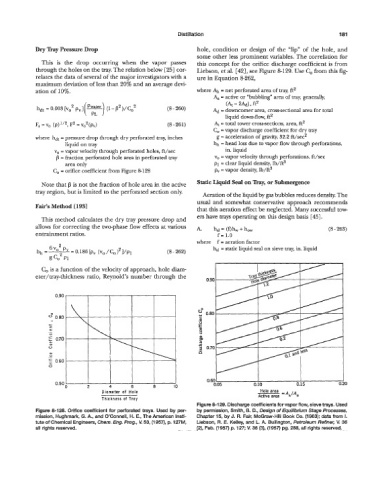
C, = orifice coefficient from Figure 8-128 pv = vapor density, Ib/ft3
Note that f3 is not the fraction of hole area in the active Static Liquid Seal on Tray, or Submergence
tray region, but is limited to the perforated section only.
Aeration of the liquid by gas bubbles reduces density. The
usual and somewhat conservative approach recommends
Fair’s Method [1931
that this aeration effect be neglected. Many successful tow-
ers have trays operating on this design basis [45].
This method calculates the dry tray pressure drop and
allows for correcting the two-phase flow effects at various A. hsl= (Qhw + how (8 - 263)
entrainment ratios. f = 1.0
where f = aeration factor
h,l = static liquid seal on sieve my, in. liquid
(8- 262)
C, is a function of the velocity of approach, hole diam-
eter/tray-thickness ratio, Reynold’s number through the
0.90
0” 0.80
e
c
a0
.-
.-
0
= 0.70
a9 0
V
._
0
0)
I 0.60
0
I I I I I 0.60 I I I
0.50; 2 4 6 8 10 0.05 0.10 0.15 0. !O
Diameter of Hole Hole area -AhIAa
Active area
Thickness of Tray
Figure 8-129. Discharge coefficients for vapor flow, sieve trays. Used
Figure 8-128. Orifice coefficient for perforated trays. Used by per- by permission, Smith, B. D., Design of Equilibrium Stage Processes,
mission, Hughmark, G. A., and O’Connell, H. E., The American Insti- Chapter 15, by J. R. Fair, McGraw-Hill Book Co. (1 963); data from 1.
tute of Chemical Engineers, Chem. Eng. Prog., U 53, (1957), p. 127M, Liebson, R. E. Kelley, and L. A. Bullington, Petroleum Refiner, U 36
all rights reserved. (Z), Feb. (1 957) p. 127; V. 36 (3), (1 957) pg. 288, all rights reserved.