
Page 197 - Applied Process Design For Chemical And Petrochemical Plants Volume II
P. 197
186 Applied Process Design for Chemical and Petrochemical Plants
0 .25
0.25
0 1.20
0.20
0 .15
a
*a
3
0 t
0.05
0.05 ~
0.00
0.0 0.2 04 0.6 08 10 0.00
00 0.2 04 0.6 08 10
(J*c)05
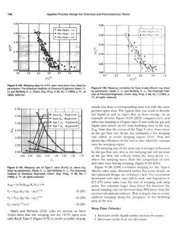
Figure 8-134. Weeping data for 9.4% open area sieve tray. Used by
permission, The American Institute of Chemical Engineers; Hsieh, C- Figure 8-136. Weeping correlation for Type-A valve (Koch) tray. Used
Li. and McNulty, K. J., Chem. Eng. Prog. V. 89, No. 7 (1993), p. 71, all by permission, Hsieh, C. Li. and McNulty, K. J., The American Insti-
rights reserved. tute of Chemical Engineers, Chem. Eng. Prog. V. 89, No. 7 (1993), p.
71, all rights reserved.
t-' the liquid as well as vapor flow as flows change. As an
0.150 nitude less than a corresponding sieve tray with the same
percent open area. The typical valve tray tends to throttle
0.125 Sieve. 4, = 50 gal/min/ft example of tests, Figure 8-133 [210] compares sieve and
0.100 Type-T. Q,., = 10 galtminltt valve tray weeping at 50 gpm/min/ft weir with the gas and
liquid rates based on the total bubbling area of the tray,
ATR. Note that the action of the Type-T valve closes down
2 0075
as the gas flow rate drops, but maintains a low weeping
0.050 rate within its entire weeping region [210]. This also
allows the efficiency of the tray to stay relatively constant
0.025 over the weeping region.
The weeping rate of the sieve tray is strongly influenced
0.000 by the gas flow rate, that is, the weeping rate will increase
000 025 050 075 100 125 150 175 as the gas flow rate reduces below the weep point, Le.,
C" where the weeping starts. Note the comparison of sieve
and valve trays during weeping, Figure 8-135 [210].
Figure 8-135. Weeping rate of Type-T valve (Koch) vs. sieve tray. Figure 8-136 [210] correlates weeping for the Type-A
Used by permission, Hsieh, C. Li. and McNulty, K. J., The American (Koch) valve trays, discussed earlier. For more details on
Institute of Chemical Engineers, Chem. Eng. Prog., V. 89, No. 7 the estimated design, see reference cited. The correlation
(1993), p. 71, all rights reserved. developed with sieve trays still is used, and Equations 8-
271-274 cover valve trays for rate of weeping and weep
R,
AVM = (n: ~HGAP N,) / 144 point. For columns larger than about 3-ft diameter the
actual weeping rate can be more than 30% lower than the
c, = VGH [pC/ (PL - PC) 1 'I2 (8 - 281)
current calculations indicate. This is largely due to a non-
CL = VLH bL/ (PL - PC) 1 1'2 (8-282) uniform weeping along the periphery of the bubbling
area of the tray.
= m cL1/2 = c (8 -283)
Weep Point (Velocity)
Hsieh and McNulty [210] (also see section on Sieve
Trays) show that the weeping rate for 14.3% open area 1. Increases as the liquid surface tension decreases
valve Koch Type-T (Figure 8-72) is nearly an order of mag- 2. Decreases as the hole size decreases