
Page 200 - Applied Process Design For Chemical And Petrochemical Plants Volume II
P. 200
Distillation 189
I .o
3.10
0.10
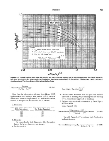
Figure 8-137. Flooding capacity, sieve trays; weir height is less than 15% of tray spacing; low- to non-foaming system; hole area at least 10%;
hole sizes %-in. to W-in. dia.; surface tension = 20 dynedcm. Used by permission, Fair, J. R., PetroKhem. Engineer, Sept (1961), p. 46, repro-
duced courtesy of Petroleum Engineer International, Dallas, Texas.
(8 - 284)
CSB, design = CSB, chart
Note that the values taken directly from Figure 8-137 4. Choose tower diameter that bill give the desired
apply to sieve trays having a hole area of 10% or more of approach to flooding. Or, if dealing with an existing
active area; holes no larger than % in., and liquid surface tower, calculate the approach to flooding.
tension of 20 dynes cm. Corrections are as follows: 5. Estimate the fractional entrainment I) from Figure
8-138 or 8-139.
a. Hole area
__ - ~. Using Figure 8-138:
HolejActive Area CSB design/CsB chart
L
0.10 1.00 Percent flood = 1 CSB,operating loo ]c=Constant (8-290)
0.08 0.90 CSB,flood
0.06 0.80
~ -- -. Use with Figure 8-137 to estimate both flood point
b. Hole size and entrainment.
No correction for hole diameter < y4 in. Correction
factors for larger diameters not known. The wet efficiency is : E, /ED = 1 (8 - 291)
c. Surface tension 1+ED (V/(l-v)