
Page 198 - Applied Process Design For Chemical And Petrochemical Plants Volume II
P. 198
Distillation 187
3. Increases as the plate thickness decreases 2. Calculate wet tray pressure drop, determine effective
4. Increases as the percentage free area increases head from Figure 8-130.
5. Increases for hole spacing close to 2d, and smaller. 3. Read weep point velocity factor, vom (p,) from Fig-
Spacing of 3d, and 4d0 give better operation. Only ure 8-131.
the %-in. holes of Hunt [33] indicate that 26 spacing The assumed value of \70’om must be greater than the
may be acceptable if the holes are very small. value read from the curve for vom (P,)’/~.
6. Decreases with increasing wettability of liquid on 4. Minimum design vapor velocity through the holes
plate surface. Kerosene, hexane, carbon tetrachlo- may be used as calculated, or if additional safety is
ride, butyl alcohol, glycerine-water mixtures all wet required increase the value by 20%.
the test plates better than pure water. The critical tray
stability data of Hunt et al., [33] is given in Table &21 Entrainment Flooding
€or air-water, and hence the velocities for other sys-
tems that wet the tray better than water should be The increasing use of sieve trays in industrial process
somewhat lower than those tabulated. The data of distillation and absorption-stripping situations has caused
Zenz [78] are somewhat higher than these tabulated the development of important performance and design
values by 10-60%. information. Flooding is caused by back-up (build-up) in
These values are to be used in guides in establishing first the downcomer and/or entrainment [ 183, 1841. When
estimates of lower limiting vapor velocities. Actual values the tray downcomers are sized to carry the liquid load and
should be calculated as outlined in the following. vapor disengagement in the downcomer (bubbles), the
The two approaches to determining the weep point are: entrainment (iet) flooding is more likely to be the con-
trolling mechanism. If the process application generates
A. Conservative Design froth, this will further complicate the flooding condition.
Most studies have used the Souders-Brown [67] droplet
1. Assume a minimum vapor velocity through the holes. settling velocity concept to relate entrainment flooding. In
2. Calculate hdr, Equation 8-260 this mechanism, flooding develops due to a sufficiently
3. Compare calculated hdt with value of dry tray pres- high upward vapor velocity through the cross-section of
sure drop as given: the net area of the column to suspend droplets, and is
hdt (weep) = 0.2 + 0.067 (hw + hoN,) expressed as the Souders-Brown flooding constant, CSB,
[94, 183, 1841.
This js based on the correlation of Mayfield [45]
where: hdt (weep) = dry tray pressure drop at tray
weep point, in. liquid.
4. Set minimum design dry tray pressure drop 30% CSB = flooding constant = C-Factor
above the value of ndt (weep).
B. Normal Design. [311
I. Assume a minimum vapor velocity through the holes. The entrainment increases as vapor velocity through
Calculate vom (p,) 112 (minimum) the column increases to a power of 2 to 5, or as small as a
10% change in vapor rate results in tenfold change in
entrainment [94]. Low pressure applications usually
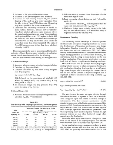
Table 821 require lower powers, while higher pressure requires high-
Tray Stability with Varying Liquid Head, Air-Water System er powers [94]. Entrainment quantities are sensitive to the
vapor velocity. Often, low pressure and vacuum applica-
Calculated Critical Gas Velocity in Holes
Ft/Sec
Hole -. . -. - - - tions develop significant entrainment problems, even
-.
h,
Dim., In. = b+ + A/2 when operating below the flood point. Medium to high
spacing, In. 1.0 h. 1.8 In. 2.8 In. 3.8 In. pressure systems are not often bothered except when
__ .. -. , . __ . , .- - - . operating at the flood point.
.
.
M x 4d0 5 2.3 32 35 Generally, when spray entrainment changes to more
X x 4d0 20 30 45 55
X x 3d0 27 40 55 70 froth on the tray or in the tray vapor space, then entrain-
!4 x 4d0 23 27 27 30 ment has been found to increase with liquid rate [941.
!4 x 6do 30 33 40 45 As tray spacing increases, entrainment reduces in quan-
.-
.
.-
- ._ . -. .- - - .- -. - - tity, but does increase with the sieve tray hole diameter
Used by permission, The American Institute of Chemical Engineers,
A.1.Ch.E. Jour Hunt, CD’X et al., V. 1, (1955), p. 441. All rights reserved. [ 183, 1841, but generally increases with reduction in hole