
Page 196 - Applied Process Design For Chemical And Petrochemical Plants Volume II
P. 196
Distillation 185
For Type-T valves: RV = 1.0 HG~ maximum lift of a valve, in.
=
For Type-A valves: RV = 0.8 HOP = valve lift, that is, the distance between the bot-
tom of a valve and the top of the tray deck, in.
Jc* = dimensionless gas velocity
Jr.* = dimensionless weeping liquid velocity
I I m = empirical constant in CCFL correlation
i 'I N, = valve density, number of valves/f<'
P rz QC" = volumetric gas flow rate to a valve, ft"/min/vaIve
R, = fractional opening in the circumference of a
valve
r12= (r, + rz)/ 2
Vc; = superficial gas velocity in channel (not ~ONCI-),
ft/s
For the valve tray equivalent hole diameter, see VGH = gas phase superficial hole velocity, ft/s
illustration. VL = superficial liquid velocity in channel (not tower),
ft/s*, for sieve trays, divide total vapor volume by
total perforated hole area
VLH = liquid phase superficial hole velocity, ft/s", for
sieve trays, divide total liquid flow by total perfo-
rated hole area
z' = Laplace capillary constant
Z = characteristic length in CCFL model
(8 - 277) * for valve trays, see calculation analysis in text
Greek letters
p~ = gas density, lbm/ft3
(8 - 278) p~, liquid density, lbm/ft"
=
0 = surface tension, dyne/cm
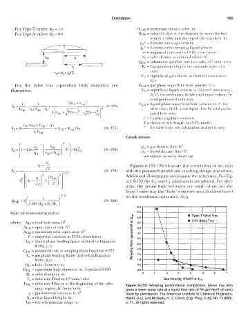
r" - r1 Figures 8-133-136 illustrate the correlation of the data
(8-279) with the proposed model and resulting design procedure.
Additional illustrations accompany the reference. For Fig-
ure 8-133 the Cv and CL parameters are plotted. For sieve
trays, the actual hole velocities are used; where for the
Type-T valve tray the "hole" velocities are calculated based
f 1 \ 1'2 on the maximum open area, Akw.
DHE = 2 (8 - 280)
2.581 (F2 + F3 ) R, )
6.0
Note: all dimensions in inches 5.5
5.0
where AH = total hole area, ft2 4.5
b p = open area of tray, ft2 4.0
AW = maximum valve open area, ft* 3.5
C = empirical constant in CCFL correlation 3.0
CL = liquid phase loading factor defined in Equation 2.5
8-282, ft/s
CLW = measured rate of weeping from Equation 8-277 2.0
C, = gas phase loading factor defined in Equation 1.5
8-281, ft/s 1 .o
DH = hole diameter, in. 0.5
DHE = equivalent hole diameter, in., Equation 8-280 0.0
D, = valve diameter, in. 0 1 2 3 4 5 6 7
F, = valve tray F-factor, ft3/min/valve Gas Velocity, ft31slft2 of A,
Fm = valve tray F-factor at the beginning of the valve Figure 8-133. Weeping performance comparison. (Valve tray also
open region, fts/min/valve gives a lower weep rate at a liquid flow rate of 50 gal/min/ft of weir.)
g = gravitational constant, ft/s* Used by permission, The American Institute of Chemical Engineers;
h, = clear liquid height, in. Hsieh, C-Li. and McNulty, K. J., Chem. Eng. Prog. V. 89, No. 7 (1993),
hD = dry tray pressure drop, in. p. 71, all rights reserved.