
Page 193 - Applied Process Design For Chemical And Petrochemical Plants Volume II
P. 193
1 82 Applied Process Design for Chemical and Petrochemical Plants
B. A second and also successful method accounts to a cer- h1= B (hw + how) (8-265)
tain extent for the aeration effect, based on test data from
many references. This method is not quite as conservative The term, hl, represents the hydrostatic head on the
when estimating total tower pressure. This follows the tray, while (h, + how) is the liquid seal at the tray outlet
effective head concept of Hughmark et al. [31]. Effective weir, expressed as clear liquid. The factor, p, can be
head, he, is the sum of the hydrostatic head plus the head obtained from the upper curve in Figure 8-126 [ 1931.
to form the bubbles and to force them through the aerat-
h
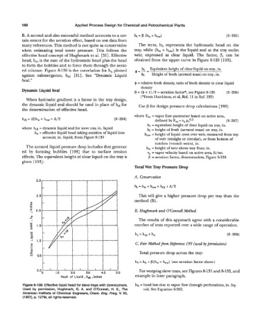
ed mixture. Figure 8-130 is the correlation for he plotted cg,l, Equivalent height of clear liquid on tray, in.
against submergence, h,l [31]. See “Dynamic Liquid h, Height of froth (aerated mass) on tray, in.
Seal.”
$ = relative froth density, ratio of froth density to clear liquid
density
Dynamic Liquid Sed f3 = ($ + 1)/2 = aeration factor*, see Figure &126 (8 266)
-
(*From Hutchison, et al, Ref. 11 in Ref. 193)
When hydraulic gradient is a factor in the tray design,
the dynamic liquid seal should be used in place of h,l for Use p for design pressure drop calculations [ 1931.
the determination of effective head.
where F, = vapor flow parameter based on active area,
-
hd = (f) h,, + h, + A/2 (8 264) defined by F, = v, p$5 (8 267)
-
hl = equivalent height of clear liquid on tray, in.
where hd = dynamic liquid seal for sieve tray, in. liquid hf = height of froth (aerated mass) on tray, in.
he = effective liquid head taking aeration of liquid into how = height of liquid crest over weir, measured from top
account, in. liquid, from Figure 8-130 of weir (straight or circular), or from bottom of
notches (v-notch weirs), in.
The aerated liquid pressure drop includes that generat- h, = height of weir above tray floor, in.
ed by forming bubbles [193] due to surface tension v, = vapor velocity based on active area, ft/sec
effects. The equivalent height of clear liquid on the tray is f3 = aeration factor, dimensionless, Figure 8126
given [193]:
Total Wet Tray Pressure Drop
A. Conservative
This will give a higher pressure drop per tray than the
method (B).
B. Hughmark and O’Connell Method
The results of this approach agree with a considerable
number of tests reported over a wide range of operation.
-
h,= hdt + he (8 268)
C. Fair Method- Reference 193 (used by pmission)
Total pressure drop across the tray:
ht = hh + B(hW + how) (see aeration factor above)
For weeping sieve trays, see Figures 8-131 and 8-132, and
Head of Liquid , h,g ,inches example in later paragraph.
Figure 8-130. Effective liquid head for sieve trays with downcomers. hh = head loss due to vapor flow through perforations, in. liq-
Used by permission, Hughmark, 0. A. and O’Connell, H. E., The uid. See Equation 8-262.
American Institute of Chemical Engineers, Chem. Eng. Pmg. V. 53,
(1 957), p. 127M, all rights reserved.