
Page 188 - Applied Process Design For Chemical And Petrochemical Plants Volume II
P. 188
Distillation 177
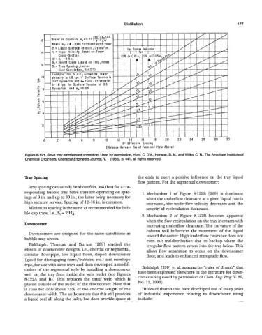
Figure 8-121. Sieve tray entrainment correction. Used by penission, Hunt, C. D’A., Hanson, D. N., and Wilke, C. R., The American Institute of
Chemical Engineers, Chemical Engineers Journal, V. 1 (1 955), p. 441, all rights reserved.
Tray Spacing the ends to exert a positive influence on the tray liquid
flow pattern. For the segmental downcomer:
Tray spacing can usually be about 6 in. less than for a cor-
responding bubble tray. Sieve trays are operating on spac- 1. Mechanism 1 of Figure 8-122B [209] is dominant
ings of 9 in. and up to 30 in., the latter being necessary for when the underflow clearance at a given liquid rate is
high vacuum service. Spacing of 12-16 in. is common. increased, the underflow velocity decreases and the
Minimum spacing is the same as recommended for bub- severity of recirculation decreases.
ble cap trays, i.e., St = 2 Hd.
2. Mechanism 2 of Figure 8-122B becomes apparent
when the flow recirculation on the tray increases with
Downcomer
increasing underflow clearance. The curvature of the
column wall influences the movement of the liquid
Downcomers are designed for the same conditions as toward the center. High underflow clearance does not
bubble tray towers. even out maldistribution due to backup where the
Biddulph, Thomas, and Burton [209] studied the irregular flow pattern enters into the tray below. This
effects of downcomer designs, i.e., chordal or segmental, allows flow separation to occur on the downcomer
circular downpipe, low liquid flows, sloped downcomer floor, and leads to enhanced retrograde flow.
(good for disengaging foam/bubbles, etc.) and envelope
type, for use with sieve trays and then developed a modifi-
cation of the segmental style by installing a downcomer Biddulph [209] et al. summarize “rules of thumb” that
weir on the tray floor inside the weir outlet (see Figures have been expressed elsewhere in the literature for down-
8-12% and B). This replaces the usual weir, which is comer sizing (used by permission of Chem. Eng. Prog. V. 89,
placed outside of the outlet of the downcomer. Note that No. 12, 1993).
it runs for only about 75% of the chordal length of the “Rules of thumb that have developed out of many years
downcomer width. The authors state that this still provides of industrial experience relating to downcomer sizing
a liquid seal all along the inlet, but does provide space at include: