
Page 191 - Applied Process Design For Chemical And Petrochemical Plants Volume II
P. 191
180 Applied Process Design for Chemical and Petrochemical Plants
This creates the same type of cross-flow and improper dis- 1.0 1, I
tribution as was discussed for bubble cap tray operation. I I I
The recommendation of Hughmark and O'Connell [31] L
includes corrections to the friction factor of Klein [39].
For stable tray operation, the hydraulic gradient should c Aeration factor
0
be less than one half the dry tray pressure drop. For con-
ditions of high weir height and high v, (p,) the greater
the friction factor affecting the hydraulic gradient [25]. 0.4 -
Also, the greater the liquid flow the higher the pressure c
drop and gradient.
For the tray liquid to move from inlet to outlet of tray,
there must be a liquid flow gradient on the tray in that LL Relative froth densit;'-
direction. See Figure 8-67A The sieve tray usually has less - 0
problems with liquid gradient than bubble cap or valve 0 0.5 1 .o 1.5 2.0 2.5
trays, the general guide to avoid gradient problems (good F"a- Vcl P P
tray stability) is similar to bubble cap design [193]: Data of FOSS and Gerster (7,
0 hw+how-5.6
Hydraulic Gradient, A = (hL - hlo), < 0.5 hh (8-254) hw+how= 1.9
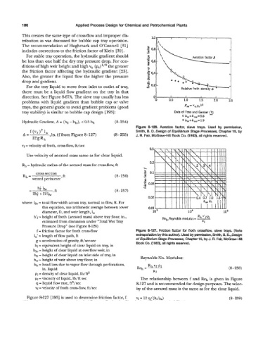
Figure 8-126. Aeration factor, sieve trays. Used by permission,
Smith, B. D. Design of Equilibrium Stage Processes, Chapter 15, by
A= f(vf)2 lW ,in.(ffromFigure8-127) (8 - 255) J. R. Fair, McGraw-Hill Book Co. (1963), all rights reserved.
12gRh
vf = velocity of froth, cross-flow, ft/sec
Use velocity of aerated mass same as for clear liquid.
Rh = hydraulic radius of the aerated mass for cross-flow, ft
cross section
Rh = I ft (8 - 256)
wetted perimeter
-
(8 257)
11 \ P,I N%
I',
0.02 0.4 0.7 1.0 1.5-'*
where lh = total flow width across tray, normal to flow, ft. For hw, in.
this equation, use arithmetic average between tower 0.01
diameter, D, and weir length, 1,
h'f = height of froth (aerated mass) above tray floor, in.,
estimated from discussion under "Total Wet Tray
Pressure Drop" (see Figure 8126)
f = friction factor for froth cross-flow Figure 8127. Friction factor for froth crossflow, sieve trays. (Note
1,' = length of flow path, ft extrapolation by this author). Used by permission, Smith, 6. D., Design
g = acceleration of gravity, ft/sec-sec of Equilibrium Stage Processes, Chapter 15, by J. R. Fair, McGraw-Hill
hl = equivalent height of clear liquid on tray, in Book Co. (1963), all rights reserved.
hl0 = height of clear liquid at overflow weir, in
hli = height of clear liquid on inlet side of tray, in Reynolds No. Modulus:
h, = height of weir above tray floor, in
hh = head loss due to vapor flow through perforations, Rh "f P1
in. liquid Reh =- (8 - 258)
p1= density of clear liquid, lb/ft3 W1
PI= viscosity of liquid, lb/ft sec The relationship between f and Reh is given in Figure
q = liquid flow rate, ft3/sec 8-127 and is recommended for design purposes. The veloc-
vf = velocity of froth cross-flow, ft/sec ity of the aerated mass is the same as for the clear liquid.
Figure 812'7 [193] is used to determine friction factor, f. vf = 12 q/ (hi k) (8 - 259)