Page 348 - Applied Process Design For Chemical And Petrochemical Plants Volume II
P. 348

Packed Towers                                          337

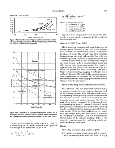
            Pressure Drop, in H20/ft
            0.7                                               I
            0.6                                    Grid A
            0.5                                                   where  V,  = vapor rate, ft?/sec
            0.4                           Grid B                       VL = liquid rate, U.S. gpm
            0.3                                                         A = tower area (JG 9)
                                                                                         f?*
            0.2                                                         h, = vapor density, lbs/ft3
            0.1                                                         p~ = liquid density, Ibs/ft3
              oj                                              I
                0.1        0.2        0.3        0.4         0.5    Typical pressure drops are shown in Figure 9-60. Mass
                               Vapor Rate, Cs, fils               transfer and heat transfer evaluations should be referred
            Figure 9-58. Nutter Snap-GridTM typical performance charts for pres-   to the manufacturer.
            sure drop. Used by permission of Nutter Engineering, Harsco Corp.,
            Bull. CSG-2, for Air-lsopar Q 1 OgpWft2.              Glitsch-GridTM [lo71 (Figure P6UU)
                                                                    This is an open area packing with multiple layers of lat-
                                                                  tice-type panels. This grid, as  described by  the manufac-
                                                                  turer’s bulletin, consists of vertical, slanted, and horizon-
                                                                  tal  planes  of  metal. The vertical strips have  horizontal
                                                                  flanges oriented alternately right and left. Due to the ran-
                                                                  dom overlap, the vapor path must zig-zag through the bed.
                                                                    Per the manufacturer, this grid has extremely low pres-
                                                                  sure drop (0.5 mm Hg/ft)  at capacities higher than is pos-
                                                                  sible with any other mass transfer device. Grid capacity is
                                                                  approximately 50% greater than conventional trays, and
                                                                  about 35%  greater than 3?4in.  ballast rings. The grid is
                                                                  highly resistant to fouling, plugging, or coking by tars or
                                                                  solids. See Figures 9-61A and 961B for pressure drop and
                                                                  capacity performance comparison. HETP is available from
                                                                  the manufkcturer and final design performance must be
                                                                  obtained from the same source.
                                                                    Structured Packing Technical Performance Features

                                                                    Fair and Bravo 11081 have performed extensive studies
                                                                  on structured packing and have developed general mod-
                                                                  els for flooding, pressure drop, and mass transfer. Struc-
                                                                  tured packing is now generally considered cost effective
                                                                  for  moderate  pressure  and  vacuum  distillations when
                                                                  compared to trays and random packings  [108]. The test
                                                                  work of  the  authors considered the  trade-named struc-
                 ”
                   0   10    20    30     40    50    60    70    tured packings of Intalox@, Gempa@, Flexipac@, Mella-
                                 Liquid Rate, Ct                  pak@, Sulzer, and Montz in their studies. See earlier fig-
                                                                  ures for installations of these packings, many of which are
                                                                  quite  similar. All  of  the  cited packings  are  corrugated
            Figure 9-59. Comparison of capacities of Flexigrid@ Styles 2 and 3   sheet type designs, except the Sulzer, which is a fabricat-
            at flooding with 2-in. Flexiring” random packing, and a competitive   ed wire  gauze construction. Table 9-38 summarizes the
            grid. Used by permission of Koch Engineering Co., Inc., Bull. KFG-2.
                                                                  characteristics  of  the  selected  packings.  Refer  to  the
                                                                  respective  manufacturers  for  confirming  details  and
                                                                  design application techniques.
                                                      >
             -4 “viscosity correction” should be made if  p~, 10.0 cp
           by  multiplying the  “%  flood” obtained from Equations   Hmding
                                              in
                                                cp.
            9-72 through 973A by the term “p~,-~~”
                                                                    At flooding or near flooding conditions [ 1081 :
                                                                    1. A rapidly increasing pressure drop with  a relatively
                                                                      slight increase in gas rate (hydraulic flood) develops.
   343   344   345   346   347   348   349   350   351   352   353