
Page 370 - Applied Process Design For Chemical And Petrochemical Plants Volume II
P. 370
Packed Towers
Avg G' = 702 ' 644 - 673 lb/ hr (ft2 )
2
1635
At inlet, L' = - = 666 lb/ hr (ft' )
1.553
At outlet, L' = 666 + 57.8 = 724
Avg L' = 666 + 724 = 696 lb/ hr (ft2 )
2
At, L' = 695, G' = 673
HOG = 1.6 ft (interpolated) based on ammonia-air-water system.
The system under study has inerts other than air.
Tower Height Based on Air as Inert Gas in System
Z e NHOG
Z = (6.33) (1.6) = 10.1 ft packing
Tmer Loading, Flooding, and Pressure o.(s
Assume 18-in. O.D. steel pipe, 16.8-in. I.D., cross-section
area is 1.553 ft2.
p~ = 62.3 lb/ft3
Ibs. NH3/iOO Ibs. He0
a
=
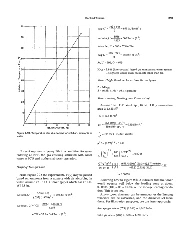
Figure 9-78. Temperature rise due to heat of solution, ammonia in - 125 for 1 - in. Berl saddles
water. 2
= (0.77)O.' = 0.949
--(-)
Curve A represents the equilibrium condition for water L(a)o'5 695 0.324 "' P0.0744
entering at 90°F, the gas entering saturated with water GPL 673 62.3
vapor at 90°F and isothermal tower operation.
G2 2v2 wo.2 (673/ 3600)2 (62.3/ 62.3)' (0.949)
Height of Transfer Unit PL PG gc ($) (62.3) (0.324) (32.2) (123)
=
From Figure 9-73 the experimental HOG may be picked = 0.00635
based on ammonia from a mixture with air absorbing in Referring now to Figure 9-21D indicates that the tower
wzter. Assume an 18 O.D. tower (pipe) which has an I.D. would operate we11 below the loading zone at about
of 16.8 in.
0.00635 (lOO)/.OS = 10.6% of the merage loading condi-
At inlet, G' - 5.35 (11.6) = 702 Ib/ hr (ft' ) tion. This is too low.
A new tower diameter can be assumed, or the limiting
(.057) (1.553ft2) velocities can be calculated, and fie diameter set from
these. For illustration purposes, me the latter approach:
At outIet, G' = 702 - (0.99) (5.35) (It)
1.553 Average gas rate = (673) (1.5.53) = 1,047 Ib/hr
- 702- 57.8= 6441b/hr (ft2) Inlet gas rate = (702) (1.553) = 1,090 b/hr