
Page 113 - Artificial Intelligence for Computational Modeling of the Heart
P. 113
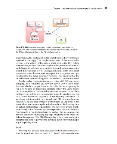
Chapter 2 Implementation of a patient-specific cardiac model 83


                     Figure 2.30. Fluid structure interaction system for cardiac haemodynamics
                     computation. The interactions between the electromechanical model, valves and
                     the CFD model are controlled by the FSI interface module.


                     at any time t, the aortic and mitral outlet surface barycenters are
                     updated accordingly. The displacement rate of the endocardial
                     vertices is the velocity information being sent to the CFD solver.
                     Furthermore, each of the valve ring boundary vertices is kinemat-
                     ically linked to a closest myocardial tetra mesh vertex, computed
                     at end-diastolic time (t = 0). During simulation, as the tetra mesh
                     moves over time, the new tetra mesh position is imposed as a rigid
                     constraint to the valve boundary vertices. This ensures that the
                     valve boundary travels along with the mesh as it moves over time.
                        Another valve constraint is ensured using a 0D–3D kinematics
                     mapping. As a reminder, the 0D valve model uses a valve phase
                     function which is proportional to the effective area opening. In
                     Fig. 2.31 we give an illustrative example of how the valve phases
                     can be mapped to 3D valve mesh sequences over the course of the
                     cardiac cycle, in this pre-computation stage. In practice one can
                     start from a kinematic sequence of topologically consistent (i.e.
                     satisfying point-to-point correspondence) 3D valve meshes (see
                     section 2.1.1) and first compute their phases as the areas of the
                     minimal surfaces spanning their rim boundaries. By focusing then
                     on a given cardiac stage (e.g. systole), one can create a valve-mesh-
                     over-systolic-time function by an interpolation method of choice.
                     For example, a Fourier transform for each of the mesh nodes has
                     also the benefit of smoothing any high frequency noise in the ini-
                     tial mesh sequence. The 0D–3D mapping is then used during the
                     computation step to provide the 3D valve mesh corresponding to
                     any 0D opening phase.

                     Step 1
                        This step has already been discussed in the biomechanics sec-
                     tion. As a reminder (see section 1.4.1), the 0D valves use the ven-