
Page 114 - Artificial Intelligence for Computational Modeling of the Heart
P. 114
84 Chapter 2 Implementation of a patient-specific cardiac model
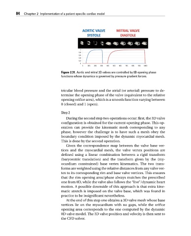
Figure 2.31. Aortic and mitral 3D valves are controlled by 0D opening phase
functions whose dynamics is governed by pressure gradient forces.
tricular blood pressure and the atrial (or arterial) pressure to de-
termine the opening phase of the valve (equivalent to the relative
opening orifice area), which is a smooth function varying between
0 (closed) and 1 (open).
Step 2
During the second step two operations occur: first, the 3D valve
configuration is obtained for the current opening phase. This op-
eration can provide the kinematic mesh corresponding to any
phase, however the challenge is to have such a mesh obey the
boundary condition imposed by the dynamic myocardial mesh.
This is done by the second operation.
Given the correspondence map between the valve base ver-
tices and the myocardial mesh, the valve vertex positions are
defined using a linear combination between a rigid transform
(barycentric translation) and the transform given by the (my-
ocardium constrained) base vertex kinematics. The two trans-
forms are weighted using the relative distances from any valve ver-
tex to its corresponding rim and base valve vertices. This ensures
that the rim opening area/phase always matches the prescribed
one from 0D, while the valve also follows the “live”/dynamic heart
motion. A possible downside of this approach is that extra kine-
matic stretch is imposed on the valve base, which was found in
practice to be insignificant nevertheless.
At the end of this step one obtains a 3D valve mesh whose base
vertices lie on the myocardium with no gaps, while the orifice
opening area corresponds to the one computed by the dynamic
0D valve model. The 3D valve position and velocity is then sent to
the CFD solver.