
Page 299 - 05. Subyek Teknik Mesin - Automobile Mechanical and Electrical Systems Automotive Technology Vehicle Maintenance and Repair (Vehicle Maintenance Repr Nv2) by Tom Denton
P. 299
3
282 Automobile mechanical and electrical systems
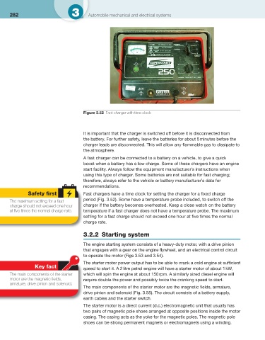
Figure 3.52 Fast charger with time clock
It is important that the charger is switched off before it is disconnected from
the battery. For further safety, leave the batteries for about 5 minutes before the
charger leads are disconnected. This will allow any fl ammable gas to dissipate to
the atmosphere.
A fast charger can be connected to a battery on a vehicle, to give a quick
boost when a battery has a low charge. Some of these chargers have an engine
start facility. Always follow the equipment manufacturer’s instructions when
using this type of charger. Some batteries are not suitable for fast charging;
therefore, always refer to the vehicle or battery manufacturer’s data for
recommendations.
Safety fi rst Fast chargers have a time clock for setting the charger for a fi xed charge
period ( Fig. 3.52 ). Some have a temperature probe included, to switch off the
The maximum setting for a fast
charge should not exceed one hour charger if the battery becomes overheated. Keep a close watch on the battery
at fi ve times the normal charge rate. temperature if a fast charger does not have a temperature probe. The maximum
setting for a fast charge should not exceed one hour at fi ve times the normal
charge rate.
3.2.2 Starting system
The engine starting system consists of a heavy-duty motor, with a drive pinion
that engages with a gear on the engine fl ywheel, and an electrical control circuit
to operate the motor ( Figs 3.53 and 3.54 ).
The starter motor power output has to be able to crank a cold engine at suffi cient
Key fact
speed to start it. A 2 litre petrol engine will have a starter motor of about 1 kW,
The main components of the starter which will spin the engine at about 150 rpm. A similarly sized diesel engine will
motor are the magnetic fi elds, require double the power and possibly twice the cranking speed to start.
armature, drive pinion and solenoid.
The main components of the starter motor are the magnetic fi elds, armature,
drive pinion and solenoid ( Fig. 3.55 ). The circuit consists of a battery supply,
earth cables and the starter switch.
The starter motor is a direct current (d.c.) electromagnetic unit that usually has
two pairs of magnetic pole shoes arranged at opposite positions inside the motor
casing. The casing acts as the yoke for the magnetic poles. The magnetic pole
shoes can be strong permanent magnets or electromagnets using a winding.