
Page 302 - 05. Subyek Teknik Mesin - Automobile Mechanical and Electrical Systems Automotive Technology Vehicle Maintenance and Repair (Vehicle Maintenance Repr Nv2) by Tom Denton
P. 302
3
Electrical systems 285
Figure 3.58 Starter in position to mesh with a ring gear on the engine fl ywheel Figure 3.59 Pinion movement
In a pre-engaged starter motor, the drive pinion is brought into mesh by the
action of an electromagnetic solenoid mounted on the starter motor casing
( Fig. 3.59 ). The solenoid has a soft iron plunger, which is drawn into the magnetic
fi eld that is produced inside the solenoid when an electrical current is passed
through the solenoid windings. Connected to the plunger is a lever, which is
pivoted so that, as one end is pulled into the solenoid, the opposite end pushes
the pinion into mesh with the starter ring gear. The pinion is mounted on a
unidirectional clutch, which is fi tted to a sleeve with an internal spline to take the
drive from the starter spindle. On the outside of the sleeve is a radial groove to
take the fork of the engagement lever.
At the other end of the solenoid are the electrical contacts that form the switch Figure 3.60 One-way clutch behind the
to pass the electrical current to the motor. The solenoid on many pre-engaged drive pinion
starter motors has two windings. These are the ‘closing’ and ‘holding’ windings.
The closing winding or pull-in coil operates as soon as the solenoid is energized.
1 4 5
This winding has an earth, or ground, return through the motor windings. This
passes a current into the motor so that it rotates slowly during the engagement
phase. Once the switch contacts are fully engaged, the holding winding holds the
switch in place. The closing winding does not conduct once the motor current
has been switched on.
A holding coil is wound around the solenoid. This creates the magnetic fi eld 8
required to hold the solenoid in the engaged position during starting. When
the starter switch is released, a spring returns the solenoid plunger to its ‘off’
position. If the engine were to start under these conditions, it would drive the
motor spindle at an excessive speed. To prevent this occurring in pre-engaged
drive starter motors, a unidirectional overrun clutch is fi tted on the pinion
( Fig. 3.60 ). This allows the motor to drive the engine but stops the engine driving
the motor. A roller-type overrun clutch is a popular method, although a few other
types are used. These clutch units are sealed for life and require replacement if
they fail in service.
2 3 6 7
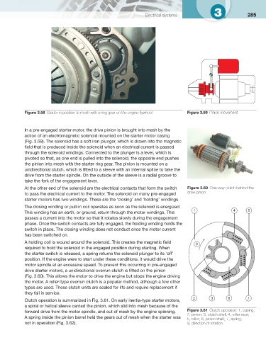
Clutch operation is summarized in Fig. 3.61 . On early inertia-type starter motors,
a spiral or helical sleeve carried the pinion, which slid into mesh because of the
forward drive from the motor spindle, and out of mesh by the engine spinning. Figure 3.61 Clutch operation: 1, casing;
2, pinion; 3, clutch shell; 4, roller race;
A spring inside the pinion barrel held the gears out of mesh when the starter was
5, roller; 6, pinion shaft; 7, spring;
not in operation ( Fig. 3.62 ). 8, direction of rotation