
Page 301 - 05. Subyek Teknik Mesin - Automobile Mechanical and Electrical Systems Automotive Technology Vehicle Maintenance and Repair (Vehicle Maintenance Repr Nv2) by Tom Denton
P. 301
3
284 Automobile mechanical and electrical systems
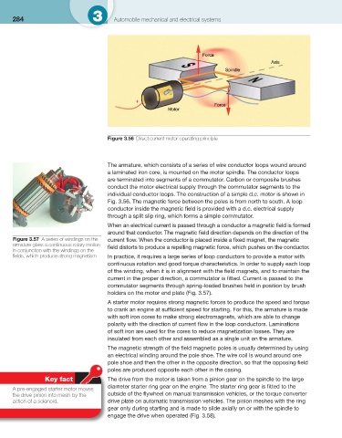
Figure 3.56 Direct current motor operating principle
The armature, which consists of a series of wire conductor loops wound around
a laminated iron core, is mounted on the motor spindle. The conductor loops
are terminated into segments of a commutator. Carbon or composite brushes
conduct the motor electrical supply through the commutator segments to the
individual conductor loops. The construction of a simple d.c. motor is shown in
Fig. 3.56 . The magnetic force between the poles is from north to south. A loop
conductor inside the magnetic fi eld is provided with a d.c. electrical supply
through a split slip ring, which forms a simple commutator.
When an electrical current is passed through a conductor a magnetic fi eld is formed
around that conductor. The magnetic fi eld direction depends on the direction of the
Figure 3.57 A series of windings on the current fl ow. When the conductor is placed inside a fi xed magnet, the magnetic
armature gives a continuous rotary motion fi eld distorts to produce a repelling magnetic force, which pushes on the conductor.
in conjunction with the windings on the
fi elds, which produce strong magnetism In practice, it requires a large series of loop conductors to provide a motor with
continuous rotation and good torque characteristics. In order to supply each loop
of the winding, when it is in alignment with the fi eld magnets, and to maintain the
current in the proper direction, a commutator is fi tted. Current is passed to the
commutator segments through spring-loaded brushes held in position by brush
holders on the motor end plate ( Fig. 3.57 ).
A starter motor requires strong magnetic forces to produce the speed and torque
to crank an engine at suffi cient speed for starting. For this, the armature is made
with soft iron cores to make strong electromagnets, which are able to change
polarity with the direction of current fl ow in the loop conductors. Laminations
of soft iron are used for the cores to reduce magnetization losses. They are
insulated from each other and assembled as a single unit on the armature.
The magnetic strength of the fi eld magnetic poles is usually determined by using
an electrical winding around the pole shoe. The wire coil is wound around one
pole shoe and then the other in the opposite direction, so that the opposing fi eld
poles are produced opposite each other in the casing.
Key fact The drive from the motor is taken from a pinion gear on the spindle to the large
diameter starter ring gear on the engine. The starter ring gear is fi tted to the
A pre-engaged starter motor moves
the drive pinion into mesh by the outside of the fl ywheel on manual transmission vehicles, or the torque converter
action of a solenoid. drive plate on automatic transmission vehicles. The pinion meshes with the ring
gear only during starting and is made to slide axially on or with the spindle to
engage the drive when operated ( Fig. 3.58 ).