
Page 306 - 05. Subyek Teknik Mesin - Automobile Mechanical and Electrical Systems Automotive Technology Vehicle Maintenance and Repair (Vehicle Maintenance Repr Nv2) by Tom Denton
P. 306
3
Electrical systems 289
Figure 3.67 Alternator
Figure 3.68 Stator and rotor
1
9 2
3
4
5
6
7
8
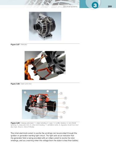
Figure 3.69 Cutaway alternator: 1, stator winding; 2, case; 3, rectifi er diodes; 4, rotor (fi eld)
winding; 5, claw pole rotor; 6, drive end bearing; 7, ventilation slots; 8, regulator, brush box and
slip rings. (Source: Bosch Media)
The initial electrical current to excite the windings can be provided through the
ignition or generator warning light circuit. The light acts as an indicator that
the generator fi eld is being provided with an initial current to excite the rotor
windings, and as a warning when the voltage from the stator is less than battery