
Page 304 - 05. Subyek Teknik Mesin - Automobile Mechanical and Electrical Systems Automotive Technology Vehicle Maintenance and Repair (Vehicle Maintenance Repr Nv2) by Tom Denton
P. 304
3
Electrical systems 287
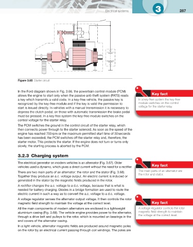
Figure 3.65 Starter circuit
In the Ford diagram shown in Fig. 3.66 , the powertrain control module (PCM)
Key fact
allows the engine to start only when the passive anti-theft system (PATS) reads
a key which transmits a valid code. In a key-free vehicle, the passive key is In a key-free system the key-free
recognized by the key-free module and if the key is valid the permission to module switches on the control
voltage for the starter relay.
start is issued directly. In vehicles with a manual transmission it is necessary to
depress the clutch pedal; on those with automatic transmission the brake pedal
must be pressed. In a key-free system the key-free module switches on the
control voltage for the starter relay.
The PCM switches the ground in the control circuit of the starter relay, which
then connects power through to the starter solenoid. As soon as the speed of the
engine has reached 750 rpm or the maximum permitted start time of 30 seconds
has been exceeded, the PCM switches off the starter relay and, therefore, the
starter motor. This protects the starter. If the engine does not turn or turns only
slowly, the starting process is aborted by the PCM.
3.2.3 Charging system
The electrical generator on modern vehicles is an alternator ( Fig. 3.67 ). Older
Key fact
vehicles used a dynamo, which gives a direct current without the need for a rectifi er.
The main parts of an alternator are
There are two main parts of an alternator: the rotor and the stator ( Fig. 3.68 ).
the rotor and stator.
Together they produce an a.c. voltage output. An electric current is induced or
generated in the stator by the magnetic fi elds produced in the rotor.
A rectifi er changes the a.c. voltage to a d.c. voltage, because that is what is
needed for battery charging. Diodes in a bridge formation are used to route the
electric current in such a way as to convert the a.c. voltage to a d.c. voltage.
A voltage regulator senses the alternator output voltage. It then controls the rotor
magnetic fi eld strength to maintain the voltage at the correct level. Key fact
All the main components of modern alternators are enclosed in a lightweight A voltage regulator controls the rotor
aluminium casing ( Fig. 3.69 ). The vehicle engine provides power to the alternator, magnetic fi eld strength to maintain
the voltage at the correct level.
through a drive belt and pulleys to the rotor, which is mounted on bearings in the
end covers of the alternator casing.
In a light vehicle, alternator magnetic fi elds are produced around magnetic poles
on the rotor by an electrical current passing through coil windings. The poles are