
Page 307 - 05. Subyek Teknik Mesin - Automobile Mechanical and Electrical Systems Automotive Technology Vehicle Maintenance and Repair (Vehicle Maintenance Repr Nv2) by Tom Denton
P. 307
3
290 Automobile mechanical and electrical systems
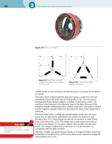
Figure 3.70 Stator construction
Figure 3.71 Star stator windings
showing main output and a tapping Figure 3.72 Delta stator windings
from the centre showing main output
voltage. Under normal conditions, the light should go out as soon as the engine
is running.
The stator, which is fi tted inside the alternator casing, is made from soft iron
laminations wound with three sets of windings ( Fig. 3.70 ). The three sets of
windings give three separate outputs, or phases, of alternating current. The
electrical current induced in the alternator fl ows in the stator because of the
changing magnetic fi elds produced by rotation of the rotor. The speed of rotation
and the magnetic strength of the rotor determine the value of the voltage that is
produced.
The three-phase stator windings are enamel-coated copper wire of a heavy
gauge and, for light vehicle applications, are usually connected in a ‘star’
formation ( Fig. 3.71 ). The windings can also be connected in a ‘delta’ (Greek
letter Δ) formation ( Fig. 3.72 ). The voltage and current outputs from the two
Key fact formations are different for the same magnetic fi eld strength and alternator
speed. The voltage is higher and current lower for the star formation, in
Alternator rectifi ers use
semiconductor diodes in a bridge comparison with the delta formation.
formation. Alternator rectifi ers use semiconductor diodes, in a bridge formation, to provide
rectifi cation of the alternating current to the direct current required to charge the
vehicle battery ( Fig. 3.73 ).