
Page 309 - 05. Subyek Teknik Mesin - Automobile Mechanical and Electrical Systems Automotive Technology Vehicle Maintenance and Repair (Vehicle Maintenance Repr Nv2) by Tom Denton
P. 309
3
292 Automobile mechanical and electrical systems
B+
D+
B−
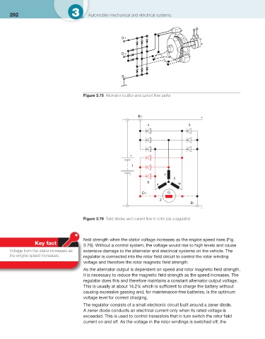
Figure 3.75 Alternator rectifi er and current fl ow paths
B+ +
4 5
+
1
− v
3
6
u w
D+ G
2 B−
−
Figure 3.76 Field diodes and current fl ow to rotor (via a regulator)
fi eld strength when the stator voltage increases as the engine speed rises ( Fig.
Key fact
3.76 ). Without a control system, the voltage would rise to high levels and cause
Voltage from the stator increases as extensive damage to the alternator and electrical systems on the vehicle. The
the engine speed increases. regulator is connected into the rotor fi eld circuit to control the rotor winding
voltage and therefore the rotor magnetic fi eld strength.
As the alternator output is dependent on speed and rotor magnetic fi eld strength,
it is necessary to reduce the magnetic fi eld strength as the speed increases. The
regulator does this and therefore maintains a constant alternator output voltage.
This is usually at about 14.2 V, which is suffi cient to charge the battery without
causing excessive gassing and, for maintenance-free batteries, is the optimum
voltage level for correct charging.
The regulator consists of a small electronic circuit built around a zener diode.
A zener diode conducts an electrical current only when its rated voltage is
exceeded. This is used to control transistors that in turn switch the rotor fi eld
current on and off. As the voltage in the rotor windings is switched off, the