
Page 305 - 05. Subyek Teknik Mesin - Automobile Mechanical and Electrical Systems Automotive Technology Vehicle Maintenance and Repair (Vehicle Maintenance Repr Nv2) by Tom Denton
P. 305
3
288 Automobile mechanical and electrical systems
2
1
3
6
HS-CAN
7 8 4
9
5
10 11
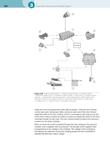
Figure 3.66 Keyless starting system: 1, keyless vehicle module; 2, start/stop button;
3, electronic steering lock; 4, powertrain control module; 5, crank sensor; 6, keyless vehicle
antenna; 7, vehicles with manual transmission: clutch pedal position switch/vehicles with
automatic transmission: stoplamp switch; 8, transmission range sensor; 9, starter relay;
10, starter motor, 11, battery. (Source: Ford Motor Company )
made from iron and shaped like claws with six fi ngers. There are two of these,
one for each pole, facing each other, and set at each end of the rotor. Wound
inside the poles is the rotor winding, which is connected to slip rings at one end
of the rotor. Carbon brushes are used to conduct an electrical current to the rotor
windings through the slip rings. The rotor rotates inside the stator and induces a
current into the stator windings.
When an electrical current is passed through the rotor windings, they become
‘excited’ and a magnetic fi eld is produced. The strength of the magnetic fi eld
is proportional to the voltage in the windings. The voltage in the windings is
provided by the alternator during the charging phase and then controlled to
regulate the alternator output voltage.