
Page 303 - 05. Subyek Teknik Mesin - Automobile Mechanical and Electrical Systems Automotive Technology Vehicle Maintenance and Repair (Vehicle Maintenance Repr Nv2) by Tom Denton
P. 303
3
286 Automobile mechanical and electrical systems
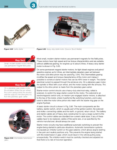
Figure 3.62 Inertia starter Figure 3.63 Heavy-duty starter motor. (Source: Bosch Media)
Most small, modern starter motors use permanent magnets for the fi eld poles.
Key fact
These motors have high speed and low torque characteristics and are suitable,
Small, modern starter motors tend to without additional gearing, for engines up to about 2 litres. A heavy-duty starter
use permanent magnet fi eld poles. motor is shown in Fig. 3.63 .
On some permanent magnet starter motors, for light diesel engines and petrol/
gasoline engines up to 5 litres, an intermediate planetary gear set between
the motor and drive pinion may be used ( Fig. 3.64 ). This intermediate gearing
modifi es the speed and torque characteristics of the motor and makes it
possible to construct starter motors that can be 40% lower in weight. The starter
electrical current is passed through the armature only. On a planetary gear motor,
Key fact the spindle is fi tted with a sun wheel, and the motor casing with the annulus. The
output to the drive pinion is made from the planetary gear carrier.
On a planetary gear starter motor,
the armature drives the sun wheel, Starter motor control circuits use a heavy-duty electrical relay, called a
the motor casing holds the annulus solenoid, to switch the large starter current to the motor. The solenoid is an
and the output to the drive pinion is electromagnetic switch and, on modern pre-engaged starter motors, is attached
from the planetary gear carrier.
to the top of the motor, where it performs the switching function, and is also
used to slide the motor drive pinion into mesh with the starter ring gear on the
engine fl ywheel.
A basic starter circuit is shown in Fig. 3.65 . The main components are the
battery, starter switch, which is usually part of the ignition switch, the solenoid
and motor, connecting cables and the earth, or ground, return circuit. The battery
and starter cables are of heavy-duty construction to carry a large current to the
motor. The control cables are standard low-current cable sizes. If any of these
cables have to be replaced, cables of the same size, or as specifi ed by the
vehicle manufacturer, should always be used.
Starter motor circuits may have additional automatic switching to prevent the
engine being started in particular situations. Automatic transmission systems
incorporate an inhibitor switch on the gear selector, which allows engine starting
in the park and neutral positions only. This prevents the engine being started
with the transmission in gear, which could result in the vehicle pulling away
unexpectedly. The inhibitor switch must be carefully checked and adjusted so
Figure 3.64 Intermediate transmission
gears that there is no risk of incorrect operation.