
Page 308 - 05. Subyek Teknik Mesin - Automobile Mechanical and Electrical Systems Automotive Technology Vehicle Maintenance and Repair (Vehicle Maintenance Repr Nv2) by Tom Denton
P. 308
3
Electrical systems 291
Figure 3.73 Rectifi er
G
a.c.
G
+
0 90 180 260 360
d.c.
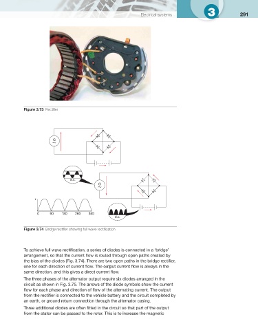
Figure 3.74 Bridge rectifi er showing full wave rectifi cation
To achieve full wave rectifi cation, a series of diodes is connected in a ‘bridge’
arrangement, so that the current fl ow is routed through open paths created by
the bias of the diodes ( Fig. 3.74 ). There are two open paths in the bridge rectifi er,
one for each direction of current fl ow. The output current fl ow is always in the
same direction, and this gives a direct current fl ow.
The three phases of the alternator output require six diodes arranged in the
circuit as shown in Fig. 3.75 . The arrows of the diode symbols show the current
fl ow for each phase and direction of fl ow of the alternating current. The output
from the rectifi er is connected to the vehicle battery and the circuit completed by
an earth, or ground return connection through the alternator casing.
Three additional diodes are often fi tted in the circuit so that part of the output
from the stator can be passed to the rotor. This is to increase the magnetic