
Page 204 - Automotive Engineering Powertrain Chassis System and Vehicle Body
P. 204
CH AP TER 8 .1 Types of suspension and drive
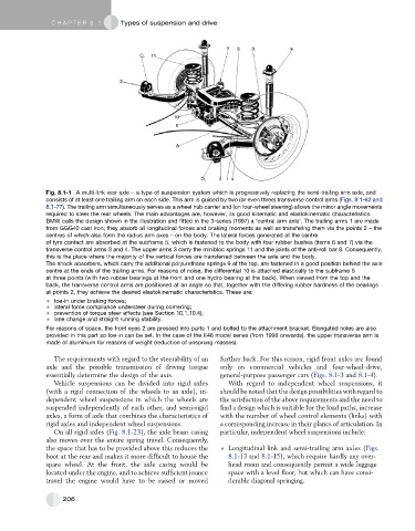
Fig. 8.1-1 A multi-link rear axle – a type of suspension system which is progressively replacing the semi-trailing arm axle, and
consists of at least one trailing arm on each side. This arm is guided by two (or even three) transverse control arms (Figs. 8.1-62 and
8.1-77). The trailing arm simultaneously serves as a wheel hub carrier and (on four-wheel steering) allows the minor angle movements
required to steer the rear wheels. The main advantages are, however, its good kinematic and elastokinematic characteristics.
BMW calls the design shown in the illustration and fitted in the 3-series (1997) a ‘central arm axle’. The trailing arms 1 are made
from GGG40 cast iron; they absorb all longitudinal forces and braking moments as well as transfering them via the points 2 – the
centres of which also form the radius arm axes – on the body. The lateral forces generated at the centre
of tyre contact are absorbed at the subframe 5, which is fastened to the body with four rubber bushes (items 6 and 7) via the
transverse control arms 3 and 4. The upper arms 3 carry the minibloc springs 11 and the joints of the anti-roll bar 8. Consequently,
this is the place where the majority of the vertical forces are transferred between the axle and the body.
The shock absorbers, which carry the additional polyurethane springs 9 at the top, are fastened in a good position behind the axle
centre at the ends of the trailing arms. For reasons of noise, the differential 10 is attached elastically to the subframe 5
at three points (with two rubber bearings at the front and one hydro bearing at the back). When viewed from the top and the
back, the transverse control arms are positioned at an angle so that, together with the differing rubber hardness of the bearings
at points 2, they achieve the desired elastokinematic characteristics. These are:
toe-in under braking forces;
lateral force compliance understeer during cornering;
prevention of torque steer effects (see Section 10.1.10.4);
lane change and straight running stability.
For reasons of space, the front eyes 2 are pressed into parts 1 and bolted to the attachment bracket. Elongated holes are also
provided in this part so toe-in can be set. In the case of the E46 model series (from 1998 onwards), the upper transverse arm is
made of aluminium for reasons of weight (reduction of unsprung masses).
The requirements with regard to the steerability of an further back. For this reason, rigid front axles are found
axle and the possible transmission of driving torque only on commercial vehicles and four-wheel-drive,
essentially determine the design of the axis. general-purpose passenger cars (Figs. 8.1-3 and 8.1-4).
Vehicle suspensions can be divided into rigid axles With regard to independent wheel suspensions, it
(with a rigid connection of the wheels to an axle), in- should be noted that the design possibilities with regard to
dependent wheel suspensions in which the wheels are the satisfaction of the above requirements and the need to
suspended independently of each other, and semi-rigid find a design which is suitable for the load paths, increase
axles, a form of axle that combines the characteristics of with the number of wheel control elements (links) with
rigid axles and independent wheel suspensions. a corresponding increase in their planes of articulation. In
On all rigid axles (Fig. 8.1-23), the axle beam casing particular, independent wheel suspensions include:
also moves over the entire spring travel. Consequently,
the space that has to be provided above this reduces the Longitudinal link and semi-trailing arm axles (Figs.
boot at the rear and makes it more difficult to house the 8.1-13 and 8.1-15), which require hardly any over-
spare wheel. At the front, the axle casing would be head room and consequently permit a wide luggage
located under the engine, and to achieve sufficient jounce space with a level floor, but which can have consi-
travel the engine would have to be raised or moved derable diagonal springing.
206