
Page 209 - Automotive Engineering Powertrain Chassis System and Vehicle Body
P. 209
Types of suspension and drive CHAPTER 8.1
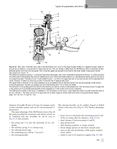
Fig. 8.1-8 Rear view of the left-hand side of the McPherson front axle on the Opel Omega (1999) with negative kingpin offset at
ground (scrub radius) r s and pendulum-linked anti-roll bar. The coil spring is offset from the McPherson strut to decrease friction
between piston rod 2 and the rod guide. Part 2 and the upper spring seat 9 are fixed to the inner wheel house panel via the
decoupled strut mount 10.
The additional elastomer spring 11 is joined to seat 9 from the inside, and on the underside it carries the dust boot 12, which contacts
the spring seat 3 and protects the chrome-plated piston rod 2. When the wheel bottoms out, the elastomer spring rests on the cap of
the supporting tube 1. Brackets 4 and 13 are welded to part 1, on which the upper ball joint of the anti-roll bar rod 5 is fastened from
inside. Bracket 13 takes the steering knuckle in between the U-shaped side arms.
The upper hole of bracket 13 has been designed as an elongated hole so that the camber can be set precisely at the factory.
A second-generation double-row angular (contact) ball bearing (item 14) controls the wheel.
The ball pivot of the guiding joint G is joined to the steering knuckle by means of clamping forces. The transverse screw 15 grips into
a ring groove of the joint bolt and prevents it from slipping out in the event of the screw loosening.
The subframe 6 is fixed to the body. In addition to the transverse control arms, it also takes the engine mounts 8 and the back of
the anti-roll bar 7. The drop centre rim is asymmetrical to allow negative wheel offset (not shown) at ground (scrub radius)
(Figs. 10.1-10, 10.1-11 and 10.1-23).
diameter of usually 30 mm or 32 mm the damper works The steering knuckle can be welded, brazed or bolted
on the twin-tube system and can be non-pressurized or firmly to the outer tube (Fig. 8.1-56). Further advantages
pressurized. are:
The main advantage of the McPherson strut is that all
the parts providing the suspension and wheel control can
lower forces in the body-side mounting points E and
be combined into one assembly. As can be seen in
D due to a large effective distance c (Fig. 8.1-5);
Fig. 8.1-8, this includes:
short distance b between points G and N;
the spring seat 3 to take the underside of the coil long spring travel;
spring; three bearing positions no longer needed;
the auxiliary spring 11 or a bump stop; better design options on the front crumple zone;
the rebound-travel stop; space at the side permitting a wide engine compart-
the underslung anti-roll bar 7 via rod 5; ment; which
the steering knuckle. makes it easy to fit transverse engines (Fig. 8.1-50).
211