
Page 213 - Automotive Engineering Powertrain Chassis System and Vehicle Body
P. 213
Types of suspension and drive CHAPTER 8.1
control arm axis of rotation EG is diagonally positioned at
an angle a ¼ 10–25 , and from the rear an angle b 5
can still be achieved. When the wheels bump and re-
bound-travel they cause spatial movement, so the drive
shafts need two joints per side with angular mobility and
length compensation (Fig. 8.1-17). The horizontal and
vertical angles determine the roll steer properties.
When the control arm is a certain length, the following
kinematic characteristics can be positively affected by
angles a and b:
height of the roll centre;
position of the radius-arm axis;
change of camber;
toe-in change;
Fig. 8.1-14 On rear axle trailing-link suspensions, the vertical
Camber and toe-in changes increase the bigger the angles
force F Z,W together with the lateral forces F Y , W cause bending
and torsional stress, making a corresponding (hollow) profile, a and b: semi-trailing axles have an elastokinematic
e.g. a closed box profile necessary. A force from inside causes tendency to oversteering.
the largest torsional moment:
T ¼ F Z;W 3 a D F Y;W 3 r dyn
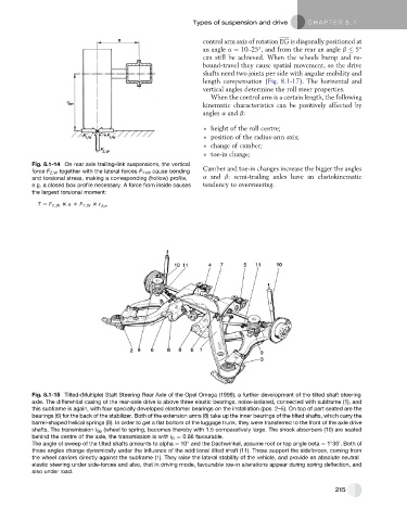
Fig. 8.1-15 Tilted-(Multiple) Staft Steering Rear Axle of the Opel Omega (1999), a further development of the tilted shaft steering
axle. The differential casing of the rear-axle drive is above three elastic bearings, noise-isolated, connected with subframe (1), and
this subframe is again, with four specially developed elastomer bearings on the installation (pos. 2–5). On top of part seated are the
bearings (6) for the back of the stabilizer. Both of the extension arms (8) take up the inner bearings of the tilted shafts, which carry the
barrel-shaped helical springs (9). In order to get a flat bottom of the luggage trunk, they were transferred to the front of the axle drive
shafts. The transmission i Sp (wheel to spring, becomes thereby with 1.5 comparatively large. The shock absorbers (10) are seated
behind the centre of the axle, the transmission is with i D ¼ 0.86 favourable.
0
The angle of sweep of the tilted shafts amounts to alpha ¼ 10 and the Dachwinkel, assume roof or top angle beta ¼ 1 35 . Both of
these angles change dynamically under the influence of the additional tilted shaft (11). These support the sideforces, coming from
the wheel carriers directly against the subframe (1). They raise the lateral stability of the vehicle, and provide an absolute neutral
elastic steering under side-forces and also, that in driving mode, favourable toe-in alterations appear during spring deflection, and
also under load.
215