
Page 214 - Automotive Engineering Powertrain Chassis System and Vehicle Body
P. 214
CH AP TER 8 .1 Types of suspension and drive
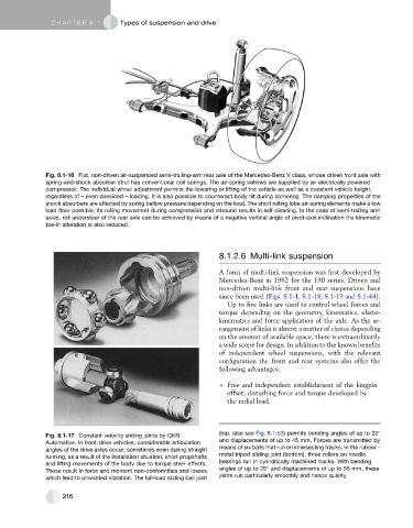
Fig. 8.1-16 Flat, non-driven air-suspended semi-trailing-arm rear axle of the Mercedes-Benz V class, whose driven front axle with
spring-and-shock absorber strut has conventional coil springs. The air-spring bellows are supplied by an electrically powered
compressor. The individual wheel adjustment permits the lowering or lifting of the vehicle as well as a constant vehicle height,
regardless of – even onesided – loading. It is also possible to counteract body tilt during cornering. The damping properties of the
shock absorbers are affected by spring bellow pressure depending on the load. The short rolling lobe air-spring elements make a low
load floor possible; its rolling movement during compression and rebound results in self-cleaning. In the case of semi-trailing arm
axles, roll understeer of the rear axle can be achieved by means of a negative vertical angle of pivot-axis inclination the kinematic
toe-in alteration is also reduced.
8.1.2.6 Multi-link suspension
A form of multi-link suspension was first developed by
Mercedes-Benz in 1982 for the 190 series. Driven and
non-driven multi-link front and rear suspensions have
since been used (Figs. 8.1-1, 8.1-18, 8.1-19 and 8.1-44).
Up to five links are used to control wheel forces and
torque depending on the geometry, kinematics, elasto-
kinematics and force application of the axle. As the ar-
rangement of links is almost a matter of choice depending
on the amount of available space, there is extraordinarily
a wide scope for design. In addition to the known benefits
of independent wheel suspensions, with the relevant
configuration the front and rear systems also offer the
following advantages:
Free and independent establishment of the kingpin
offset, disturbing force and torque developed by
the radial load.
(top, also see Fig. 8.1-53) permits bending angles of up to 22
Fig. 8.1-17 Constant velocity sliding joints by GKN
Automotive. In front-drive vehicles, considerable articulation and displacements of up to 45 mm. Forces are transmitted by
means of six balls that run on intersecting tracks. In the rubber –
angles of the drive axles occur, sometimes even during straight
running, as a result of the installation situation, short propshafts metal tripod sliding joint (bottom), three rollers on needle
bearings run in cylindrically machined tracks. With bending
and lifting movements of the body due to torque steer effects.
These result in force and moment non-conformities and losses angles of up to 25 and displacements of up to 55 mm, these
which lead to unwanted vibration. The full-load sliding ball joint joints run particularly smoothly and hence quietly.
216