
Page 219 - Automotive Engineering Powertrain Chassis System and Vehicle Body
P. 219
Types of suspension and drive CHAPTER 8.1
Fig. 8.1-27 Longitudinal rear leaf springs support the body
of a car in two places – under the back seats and under the
boot – with the advantage of reduced bodywork stress.
axle and independent wheel suspension) which, up to
now, has been fitted only on front-wheel drive vehicles.
Details are given in Fig. 8.1-2 and Section 8.1.6.4.1.
Fig. 8.1-29 If a rigid rear axle steers with the angle Dr towards
8.1.3.2 Semi rigid crank axles understeer, the tail moves out less in the bend and the driver
has the impression of more neutral behaviour. Moreover, there
The compound crank suspension could be described as the is increased safety when changing lanes quickly at speed.
new rear axle design of the 1970s (Figs. 8.1-2 and 8.1-30) The same occurs if the outside wheel of an independent wheel
and it is still used in today’s small-and medium-sized suspension goes into toe-in and the inside wheel goes into
front-wheel-drive vehicles. It consists of two trailing arms toe-out.
that are welded to a twistable cross-member and fixed to
the body via trailing links. This member absorbs all vertical
and lateral force moments and, because of its offset to the wheel centre, must be less torsionally stiff and function
simultaneously as an anti-roll bar. The axle has numerous
advantages and is therefore found on a number of pas-
senger cars which have come onto the market.
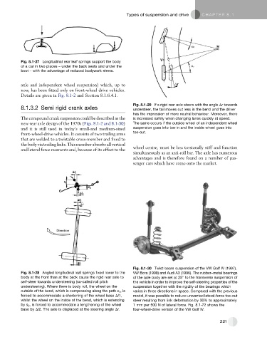
Fig. 8.1-30 Twist-beam suspension of the VW Golf IV (1997),
Fig. 8.1-28 Angled longitudinal leaf springs fixed lower to the VW Bora (1999) and Audi A3 (1996). The rubber–metal bearings
body at the front than at the back cause the rigid rear axle to of the axle body are set at 25 to the transverse suspension of
self-steer towards understeering (so-called roll pitch the vehicle in order to improve the self-steering properties of the
understeering). Where there is body roll, the wheel on the suspension together with the rigidity of the bearings which
outside of the bend, which is compressing along the path s 1 ,is varies in three directions in space. Compared with the previous
forced to accommodate a shortening of the wheel base Dl1, model, it was possible to reduce unwanted lateral-force toe-out
whilst the wheel on the inside of the bend, which is extending steer resulting from link deformation by 30% to approximately
by s 2 , is forced to accommodate a lengthening of the wheel 1 mm per 500 N of lateral force. Fig. 8.1-72 shows the
base by Dl2. The axle is displaced at the steering angle Dr. four-wheel-drive version of the VW Golf IV.
221